Rush Pinball Inner Loop Guide

Description
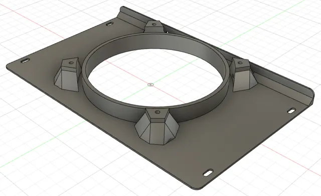
PDFThis can be attached to the top of the outer wall of the inner loop on the Stern Rush pinball machine (any variety). It provides a groove for the ball to ride in, should it ride up that outer wall as it takes the curve. The groove gradually ramps back down, to ensure that the ball is close enough to the playfield surface to trigger the roll-over switch as it goes by.
In my tests this has completely eliminated instances where shots made on the inner loop don't register.
This design fits the metal on my machine perfectly. But I don't know what the variance in manufacturing is for that part. I would expect this to slide neatly onto the top of the wall on any machine, but I can't say for sure.
When installing this, you'll need to temporarily remove the plastic above the outer wall. Position this piece along the curve, matching the shape of the piece to the shape of the curve. When it's in the right position, the "exit" end of the piece will be past the middle of the roll-over switch, and the barbed tab will be centered on the cut-out in the metal lane wall, where it can engage to hold the part in place.
It may help to push it on starting at the exit end then working your way down toward the entrance end. In any case, it will require some pressure to get the part slid completely down into its fully-seated position. Even if your machine's metal wall isn't exactly the same shape as mine, a part printed in PETG should flex enough to fit, but some may prefer to use TPU for an easier time installing.
Before installing, make sure that there's no left-over debris from printing, supports, etc. in the groove that fits over the top of the lane guide. Clearances are tight, so any little bit of crud that's not supposed to be there will prevent the part from fitting down tightly on the lane guide like it's supposed to.
Print Settings
Printer Brand:
Prusa
Printer:
I3 MK3S
Rafts:
No
Supports:
Yes
Resolution:
0.1 mm layer height
Infill:
10%
Filament: MatterHackers PETG Black
Notes:
I printed this with PETG using the settings above, a 0.4 mm nozzle, and PrusaSlicer's default profile for PETG, but it would probably print okay with other settings. The pinball doesn't actually strike the part; it will hit the metal wall before rolling along the part, so the part isn't experiencing a lot of stress. Still, some may prefer to print with TPU, either to make it easier to install, or just in case an occasional air ball might hit it.
For best results, the piece should be printed upside down, with the top flat on the print bed. The barbed tab will require supports. I printed with PrusaSlicer 2.5 and had no trouble at all with the supports. I used the "Snug" setting for the support style, and of course left "Support on build plate only" unchecked. With those settings, the support detached easily from the barb end with a utility knife blade, and then a small needle-nose pliers were used to grip the support and pull it gently out of the slot. I was left with no scarring at all inside the slot, and just a hint along the edge of the barb.
While I use support to print this, I've heard from at least one person who was able to print on their Prusa MK3S+ without supports, using PLA, limiting their print speed to 25 mm/s with an extruder temp of 215 C. Apparently, the little barb that would be supported is small enough that the overhang can be printed successfully without them.
Post-Printing
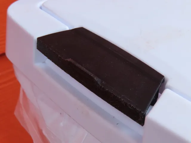
The part as installed on the top of the outer wall of the inner loop.
Category: Other
Tags
Model origin
The author marked this model as their own original creation. Imported from Thingiverse.