BTT Smart Filament Runout Sensor Mount
Description
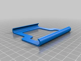
PDFDesigned to be printed at 0.2mm layer height.
Print at orientation as opened in slicer.
Minimal support required for FramePart.stl, no support required for SensorPart.stl
Finished mounting as shown in image.
HARDWARE REQUIRED
2x M3x5mmx5mm brass heated inserts
1x M3x12mm machine screw
5x M3x14mm machines screws
2x M5x45mm machine screws
SETUP & FITTING
The 2 heated sets go in the back of the FramePart, directly behind the raised block.
Attach the SensorPart to the Framepart using 1x M3x14mm & 1x M3x12mm machine screws, the shorter of the two screws is for the shallower hole in the FramePart.
These screws go through from the front of the SensorPart where the heads will be recessed.
Now remove the 4 original outer screws from the BTT Smart Filament Runout Sensor & attach it to the SensorPart front using the remaining 4x M3x14mm machines screws that come through from the back.
You will see two access holes in the FramePart to allow fitting the two bottom screws to the Smart Sensor.
Finally, attached the completed part to the printer replacing the original outer Z axis carriage guide bolts with the 2x M5x45mm machine screws, there won't be a whole lot of thread poking through the FramePart to get the nut on but once you start to tighten them, they're fine.
Happy Printing ;)
Category: 3D Printer AccessoriesTags
Model origin
The author marked this model as their own original creation. Imported from Thingiverse.


