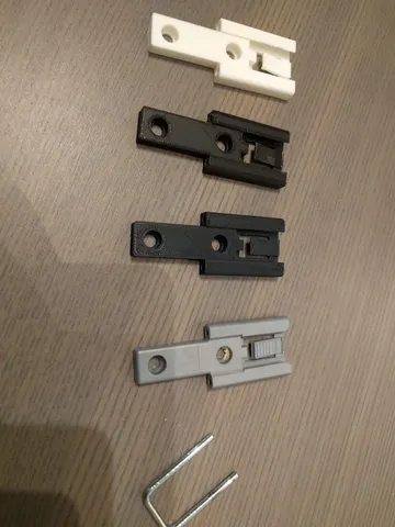
CNC3018 spindle mount

Description
PDFBefore you print
Check your CNC3018-like machine if it fits this design. I know there
are many variations of this machine with LMUU10 bearings on Z-axis instead LMUU08 and different bearings spacing. In this project the spacing between linear bearings center is 38mm which kinda explains why the trapeizodal screw has to be cut in order to fit in between.
Required items:
- 2x LM08LUU linear bearings (45mm long)
- 1x Trapezoidal screw TR8x4 (check with your machine) with anti-backlash nut (needs to be cut and grinded to fit inside the Z-axis sledge)
- 3x Hex M6 screw, nut and washer
- AC glue
You need to fix the trapezoidal screw with the spring and antibacklash-nut inside the sledge. Then check it with the trapeizodal rod if it fits properly, mechanical alignment and so on. Put the the small lid (z_axis_locker.stl) on the trapeizodal screw opening and fix it with glue with the sledge. Make sure, the glue did not get to the screw thread.
Same thing for the linear berrings - apply the glue on the inner walls of the linear bearing holes and push the bearings inside, make sure to align the bearings equally from both sides of the slege. Wait for the glue to dry.
With this design I was able to mill PCB's with accurate-enough precision for my DIY projects.
You can see example video and photos of the PCB making process here:
https://www.youtube.com/watch?v=OzJ_bb20_9I
https://photos.app.goo.gl/vLs5gWqZPQQpVirQ8
Any creative comments and questions are welcome.
Tags
Model origin
The author hasn't provided the model origin yet.