Wemos D1 Mini ESP8266 Case

Description
PDFA case for the Wemos D1 Mini ESP8266 PCB. It has holes on all 3 walls partially for ventilation but mostly for wire pass-throughs to make running wires in different directions easier. There are holes for the reset button on each side distanced properly to account for either face of the PCB being side up.
There are three tops that have been included:
- Standard - only accommodates the D1 Mini and there is just room for some wiring.
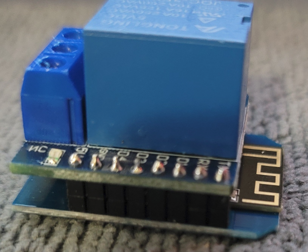
- Relay Shield - there is a D1 Mini relay shield and the top is made to allow the relay to protrude
- mmWave - compatible with this mmWave device for motion detection so there is a hole in the top to expose the sensor
The fit may seem tight, but it will go in, just make sure the “back” is aligned, going in straight, and pushed in all the way and then you should be able to push the front (USB side) down into the retaining clips. It may take a little force, but it won't hurt it (I've done plenty of testing and everything is “safe” for the parts). Taking the PCB out may be a little tough, as well, but it will also come out. If needed, a plastic spudger might be useful to lever against the base and “bottom” of the D1 Mini to push it up out of the “front” retaining clips. Don't be afraid to apply some pressure, the D1 Mini is sturdy.
NOTE: You may be able to get away with no supports. I did not try to print without supports for the wiring holes, but I have printed other pieces without support with similar widths on default Ender 3 Pro settings and was able to bridge. The reset button holes are definitely doable without supports as I have denied supports for them already.
MAJOR NOTE for mmWave sensor and Relay:
Both of these modules can be attached directly to the D1 Mini with GPIO pins since everything lines up. The Relay Shield is pretty straightforward since it is made to line up all holes with the D1 Mini. And the mmWave also lines up perfectly with 2 sets of 2 pins on the 5V side; very convenient for mounting. Excellent instructions on making the exact D1 Mini/mmWave sensor that I used is found here.
So, instead of using the GPIO pins with the really thick pieces of plastics (and that aren't double-sided), I used the ones with the very thin pieces of plastic holding the pins in place. In addition to this, I removed the pins from another set of these “low profile” pins and slid the plastic spacer down on the GPIO pins so that there was ample spacing between the two PCBs: makes it not too tall but close enough so they don't touch. By making these spacers, it allows for a small profile case/mmwave top combo that will work with my print and makes it very easy to solder the boards together.
This is the only way you will be able to get the combined modules to fit inside my case with the associated tops since this is the spacing I used.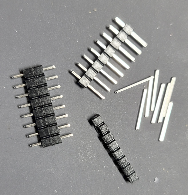
Tags
Model origin
The author hasn't provided the model origin yet.