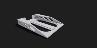
Prusa Mini LCD backplate
Description
PDFIt's highly recommended to check the circuit board and the printed model together before you tighten the screws. Check the distance between the front plate and the LCD display while you are tightening the screws. There is a safety net in case the screws are overtightened (please check the attached .pdf) but please be careful.
On the other side, there is a rubber rim around the LCD display, that's why I created “lower” - 4,5mm - legs for the circuit board. That rim does the job so this assembly is not "clicky", the circuit board does not move even when I press the knob.
- You check the backplate in the attached solid models, and you can check my backplate together with the original Prusa part in .Shapr File.
My print settings on a Mini:
- I used Prusament PET-G (It has not been tested with PLA)
- 0.2mm Speed - built-in setting in Prusa slicer
- Infill 20%
Attachment:
Drawings with the most important dimensions:
LCD Backplate v2 Drawing.pdf
3D printable files:
Backplate_v2.3MF
Backplate_v2.STL
If you want to change something:
Backplate_v2.Shapr - backplate_v2.zip
Backplate_v2.STEP - backplate_v2.zip
Backplate_v2.X_T - backplate_v2.zip
And once again, check the distance between the front plate and the LCD display while you are tightening the screws.
Tags
Model origin
The author hasn't provided the model origin yet.


