Baddeley MKIII Drive Axle Mod
Description
PDFRegardless of what material you use to print your R2D2, the axle that runs through the drive wheel on the MKIII drives should be replaced with a steel rod for maximum strength and durability.
Although threaded rods could be used in this application, over-tightening of the nuts on either end could pinch the sides of the drive together enough to inhibit rotation of the drive wheel and affect your drive's efficiency and performance.
A better solution is to use a smooth, M8 steel rod held in place by a pair of lock collars. Cut the steel rod to about 105mm in length. Use a rotary tool to grind one side of each end flat to receive the set screws from the collars.
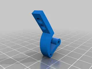
Since the original part is not being used, there are hexagonal openings on each side of the drive frame (MotorFrameB and SideFrameA) that should be filled with something for added support - that's where these parts come into play. They simply slide into each cavity until they sit flush. Fit should be reasonably tight. Each spacer has notches at one end - insert the part with the notches down. These are there so that you can insert a long allen key or screwdriver from the opposite side into these notches to push the spacer out should you need to replace it.
Assembly Order
With the steel rod for an axle, drive assembly is actually much easier, IMO, than with the stock parts.
- Position the center gear in its cavity, but leave it loose.
- Insert the motor with the motor gear securely installed.
- Make sure the motor gear and center gear mesh correctly, then secure the motor in place and insert and secure GearBoxPin to hold the middle gear in position.
- Secure the cover for the center gear (MotorBracketCover), ensuring the top of GearBoxPin rests in the circular opening.
- Insert AxleSpacer_A into the hexagonal opening on MotorFrameB (notches down) until it sits flush.
- Slide the assembled drive wheel into place (this includes bearings plus any spacers you might be using). You should be able to properly mesh the gears without much trouble.
- Slide the metal axle down through the wheel and motor frame, locking it into place.
- Insert AxleSpacer_B into the hexagonal opening on SideFrameA (notches down) until it sits flush.
- Add any necessary spacers to the drive wheel, then close the drive by sliding SideFrameA into place, making sure the steel axle extends through the hole. Secure it with all necessary hardware.
- Center the drive axle and secure it in place using a pair of lock collars.
That's it! I also highly recommend implementing both of Tim Hebel's MKIII main drive modifications which can be found on the Baddeley file share within the MKIII print files. These mods improve the strength of the center GearBoxPin (which is also prone to breaking) and provide a means of using metal flanges to attach the gear motor to the motor.
Tags
Model origin
The author hasn't provided the model origin yet.


