4x5 large format camera

Description
PDF
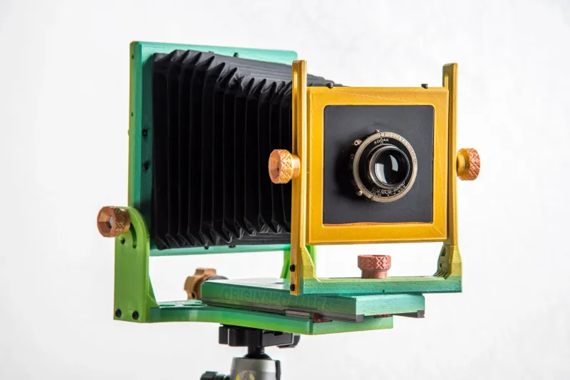
Film photography has survived and thrived in modern times; I fell in love with film from the get go. Because of it’s capability to create high quality prints I was drawn to it, and this eventually brought me to the 4x5 format; an incredibly flexible camera with an outstanding rage of movement. The distinctive quality of large format photography compels you to slow down and focus on each image in a whole different way. While on my search for a 4x5 camera, I realized that it is generally economically inaccessible to a wide audience, because of how costly a camera can be.
This camera intends to open up large format photography to a larger audience, this modern take of the large format camera creates a lightweight solution, at only 1.2kg. It is quick to set up, extremely durable and allows a wide range of movement. This design has been optimized to be printed without supports, and is divided into multiple parts so it can be printed easily.
BEFORE YOU START:
To assemble this camera, it is required to have printed all the parts and have the following list of additional components:
- 1 x Anti-Backlash Nut Block for C-Beam 8mm Lead T8 Screw 3D Printer
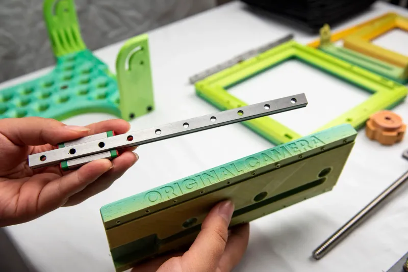
- 2 × linear slide MGN linear rails guide with mini Carriage Block
- 1 x Horizontal Ball Bearing Stepper Coupler 0.8cm Dia 20cm
- 5 x 1" Steel Hex Head Screws
- 4 x M4 Alloy Steel Socket Head Screws 16mm
- 4 x M4 Alloy Steel Nut
- 8 x M3 Alloy Steel Socket Head Screws 6mm
- 8 x M3 Alloy Steel Socket Head Screws 16mm
- 8 x M3 Alloy Steel Socket Head Screws 10mm
- 8 x M3 steel washer
- 24 x M3 Alloy Steel Nut
- 10 x M2 Alloy Steel Socket Head Screws 12mm
- 2 x Alloy Steel Flat-Tip Set Screws 3/4"
- 4 x Tapping Inserts for Plastic ¼"
- 20 x Phillips screw 5mm
- 6 x Alloy Steel Nut ¼"
TOOLS REQUIRED:
- 3D Printer
- Phillips Screwdriver
- Hex key allen wrench set
MATERIALS REQUIRED:
- 1 kg of PLA filament with a 0.4mm nozzle and 25% infill.
- 1 single bellow.
- Large format camera lens of your choice, or a pinhole lens.
- 4x5 Ground Glass Focusing Screen (I used a piece of sandblasted glass- it works just fine).
ADDITIONAL NOTES:
More infill can increase the structure's rigidity, though I've been satisfied with the 0.4mm nozzle wall thickness.
Depending on the filament, you will require more walls to ensure that light will not filter through ( I tend to use 4 walls)
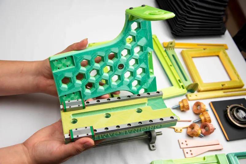
ASSEMBLY
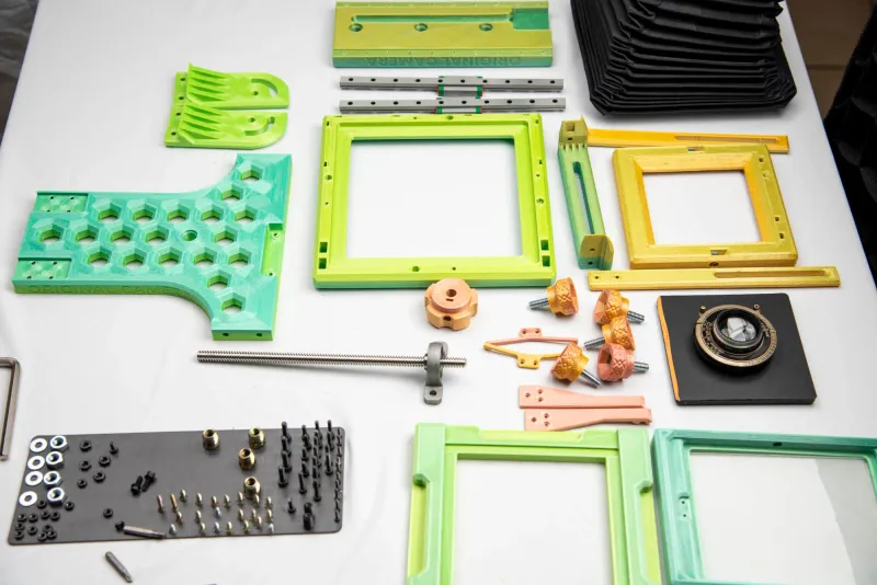
This assembly guide will guide you through the process of building your camera. You will start off with many parts, so it's best to work in an orderly fashion.
STEP 1
3D-print the various components detailed below. It's best to lay them out on a flat surface to maintain order and easy identification of the pieces.
STEP 2
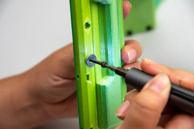
Attach the Base Sides to the Base with 4 x M4 Alloy Steel Socket Head Screws 16mm, fastening them to 4 x M4 Alloy Steel Nuts. Insert said nuts into each slit photographed here.
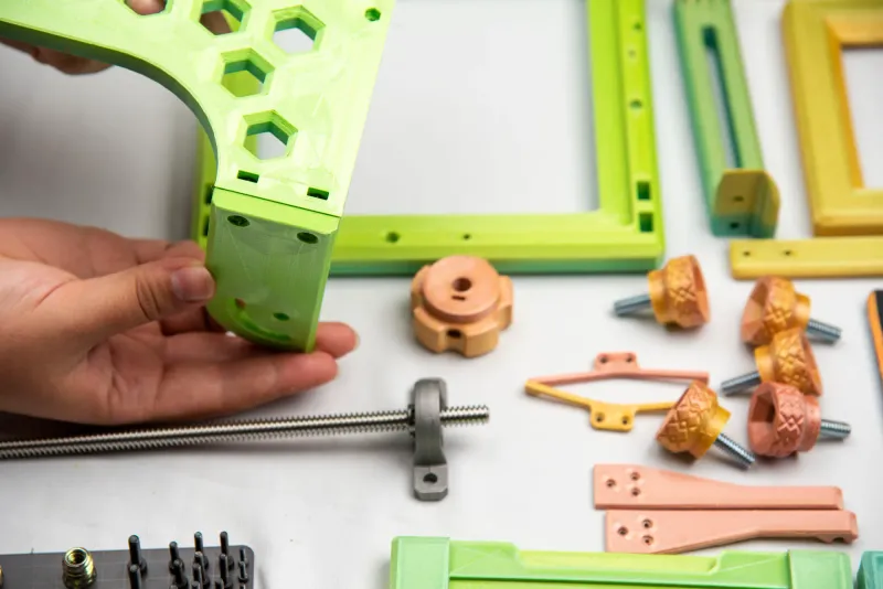
As you can see there are two slits per side, so that each screw may have a nut fastened to it.
STEP 3
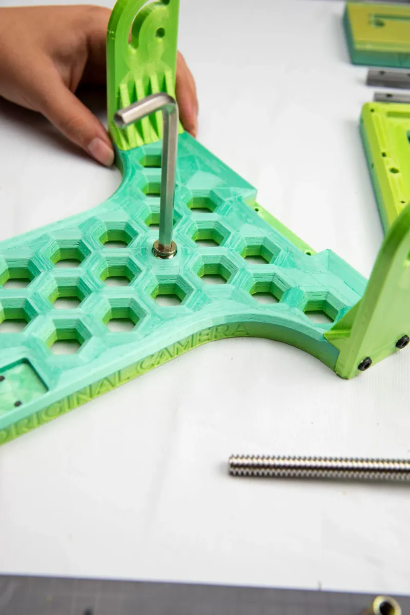
Using your Hex key allen wrench set attach the ¼" Tapping Inserts for Plastic to the Base. We'll set aside our Base piece for now.
STEP 4
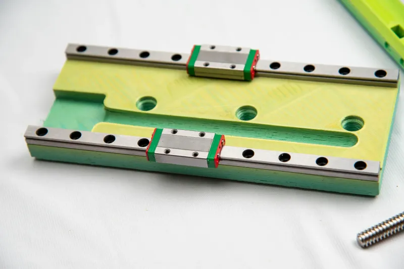
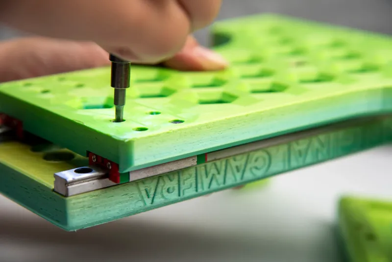
Now we will attach our 2 × linear slide MGN linear rails guide with mini Carriage Block to our Base For Rails piece.
For easy workflow, place your Base for Rails upside down on a flat surface. Make sure that you maintain the mini Carriage Blocks centered on the rails to prevent them from slipping off- another alternative is to tape them down just for this step.
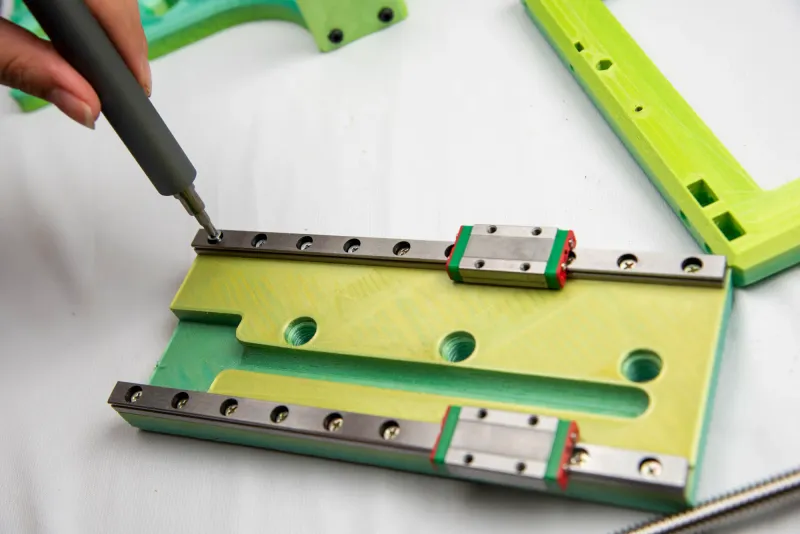
Place and screw in 20 x Phillips screw 5mm to the linear slide MGN linear rails.
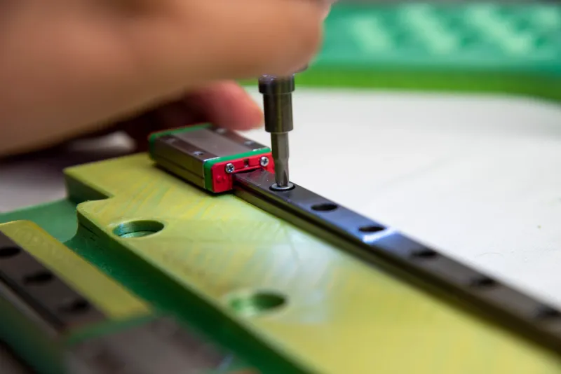
Screws should be completely sunken into the hole provided on the rails- if not you will be prevented from having camera movement.
STEP 5
Maintaining the Base For Rails upside down, we can now attach the remaining ¼" Tapping Inserts for Plastic to the Base For Rails.
Using your Hex key allen wrench set attach the ¼" Tapping Inserts for Plastic to the Base.
STEP 6
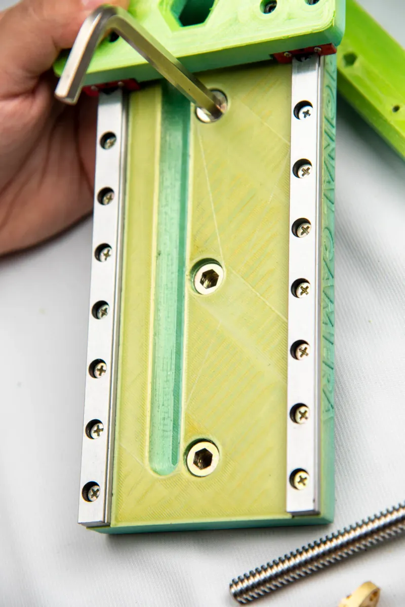
Now, we will come back to our Base piece and attach the Base For Rails to it. Placing both pieces upside down, the Base piece will have 2 indents where each mini Carriage Blocks will fit into.
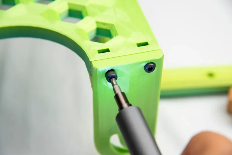
Secure each mini Carriage Blocks to Base with 4 M3 Alloy Steel Socket Head Screws 6mm.
STEP 7
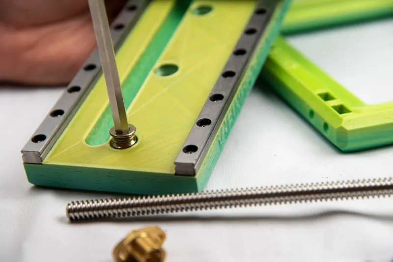
We can finally flip our piece around, right side up, and insert the Horizontal Ball Bearing Stepper Coupler between the Base piece and the Base for Rails pieces that are now attached. You will find and opening for this.
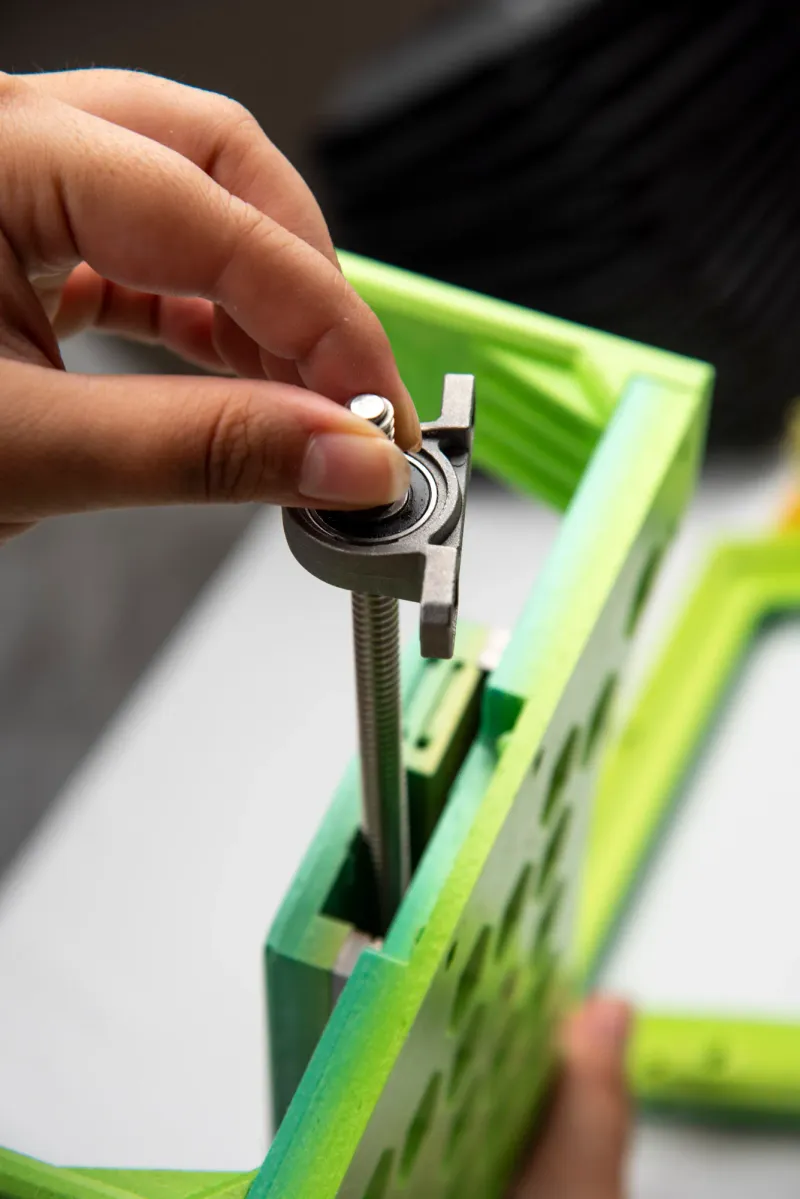
Attach the Horizontal Ball Bearing Stepper Coupler to the Base piece with 2 M3 Alloy Steel Socket Head Screws 10mm, one on each side.
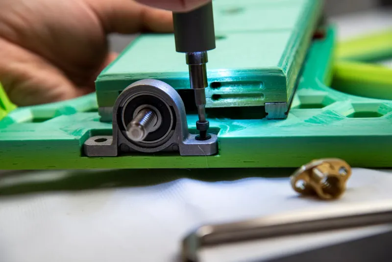
Place 2 M3 Alloy Steel Nut on the other end to secure screws.
STEP 8
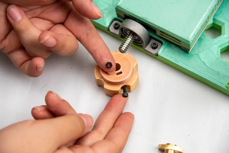
Attach the Big Knob to the Horizontal Ball Bearing Stepper Coupler with M3 Alloy Steel Socket Head Screws 10mm, by inserting a M3 Alloy Steel Nut into the slot (photographed) to secure the screw. We'll set this whole piece aside for now.
STEP 9
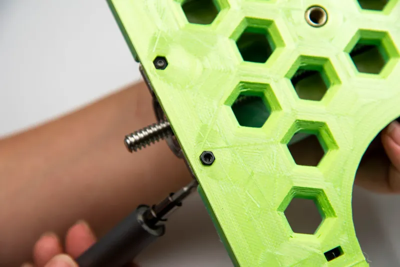
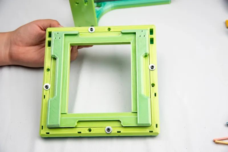
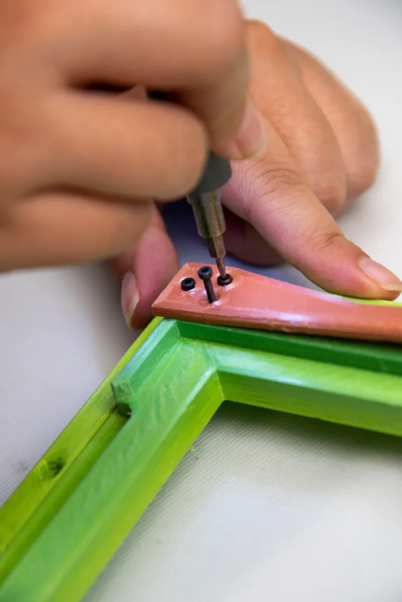
Attach the Frame For Ground Glass Holder to the Rear Frame, by placing the Rear frame over the Holder.
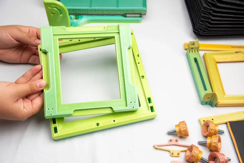
Place a M3 steel washer under a M3 Alloy Steel Socket Head Screws 16mm and attach to Frame For Ground Glass Holder.
In total you will place 4 M3 steel washer under 4 M3 Alloy Steel Socket Head Screws 16mm.
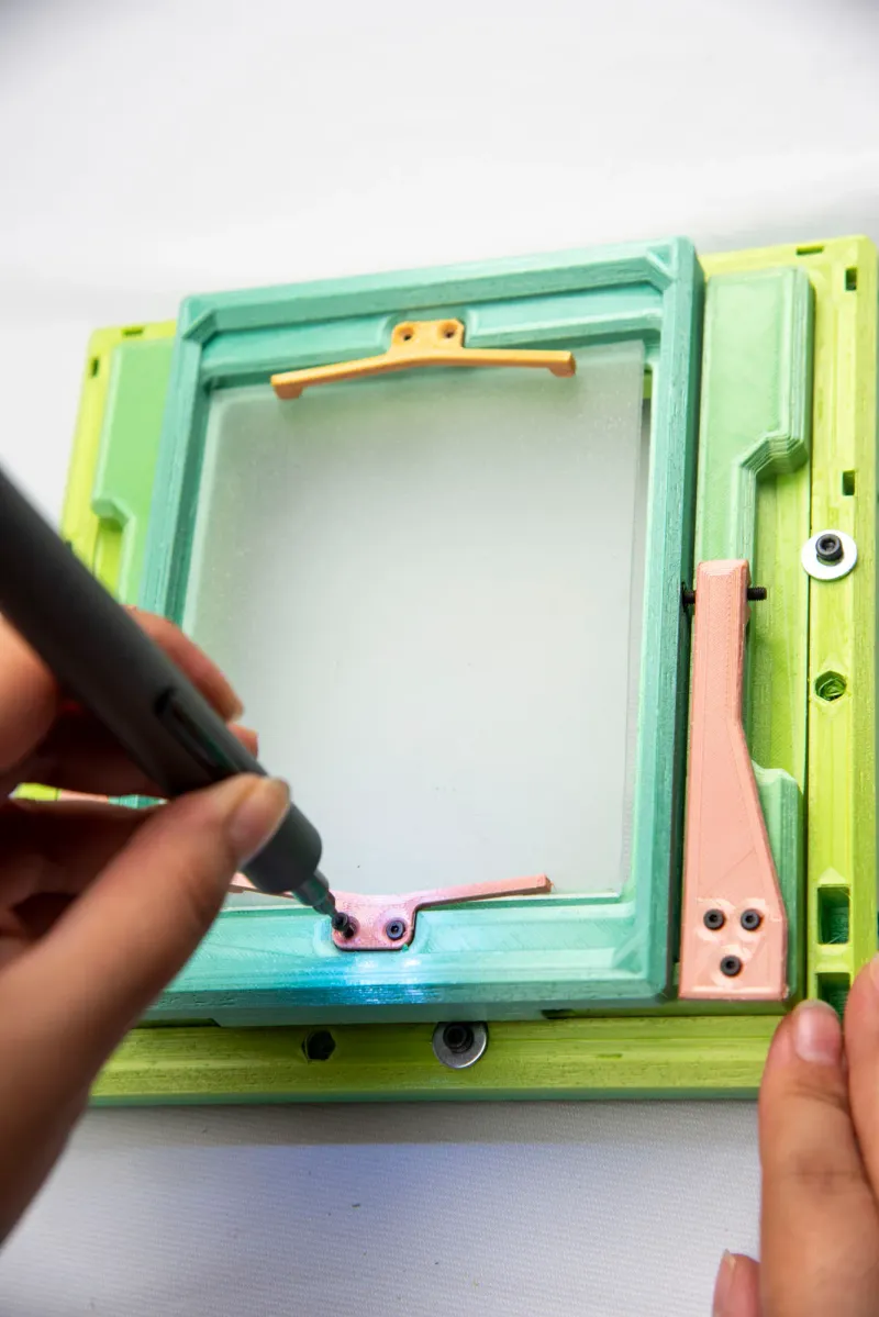
STEP 10
We will now attach the Glass Holder Springs to the Frame For Ground Glass Holder.
Using 3 M2 Alloy Steel Socket Head Screws 12mm o each side, we will attach the Glass Holder Springs to the Frame For Ground Glass Holder. We will momentarily set this piece aside.
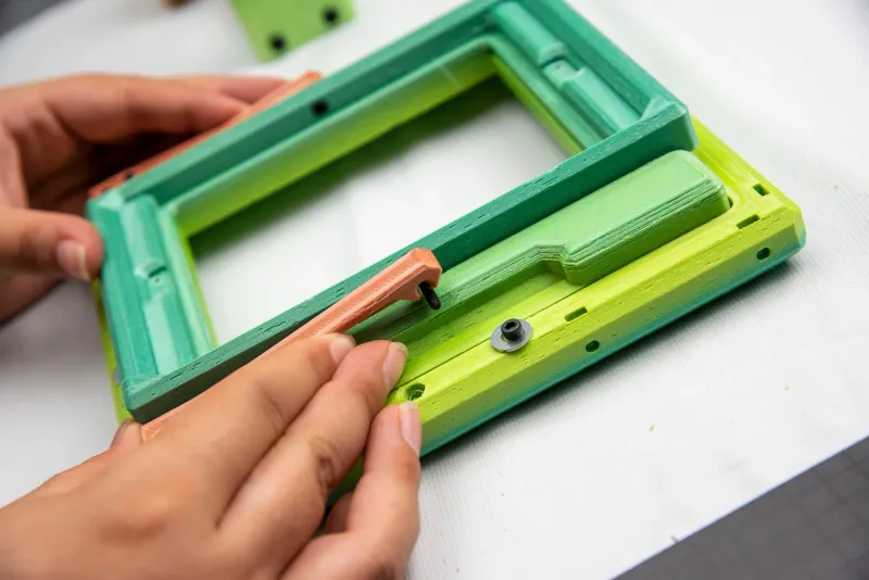
STEP 11
We will get our Glass Holder and attach a M3 Alloy Steel Socket Head Screws 10mm to each side, using a M3 Alloy Steel Nut to hold it securely in place.
With both screws attached, we are ready to insert it into the Glass Holder Frame.
We can pick our Frame for Glass Holder back up.
Glass Holder Srings should snugly hold the Glass Holder in place
STEP 12
We can now insert our glass into the Glass into the Glass Holder.
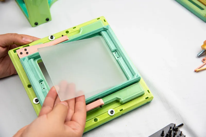
Now, place our Glass Insurance pieces over the glass and screw them in place with 2 M2 Alloy Steel Socket Head Screws 12mm each.
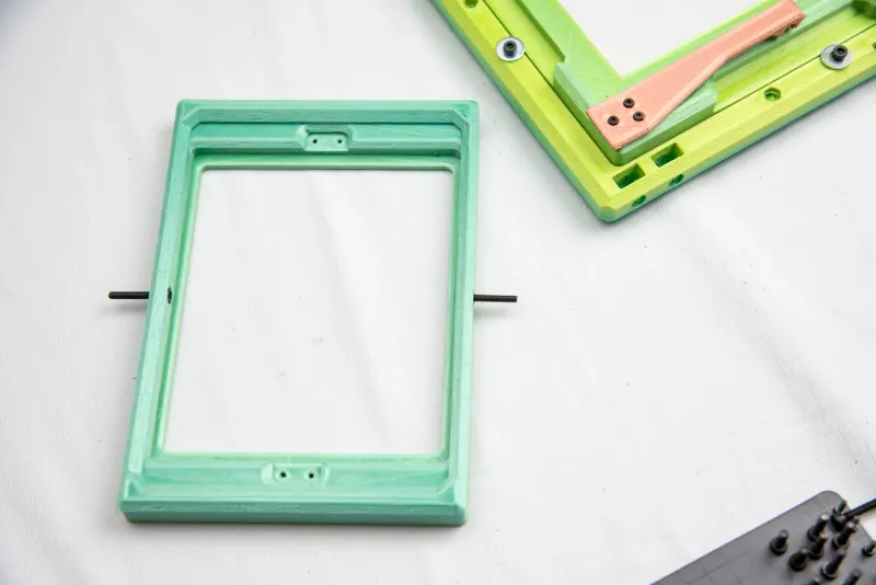
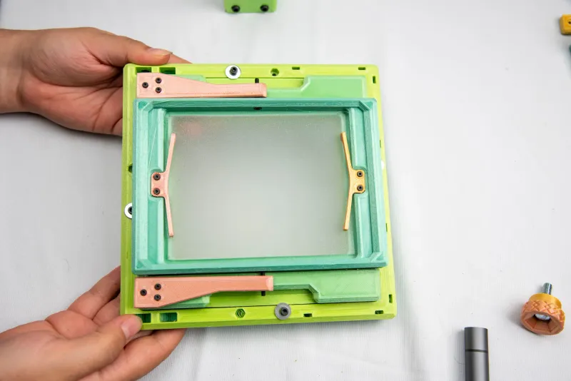
Good job! Your back plate should be looking something like this:
STEP 13
We will now place an Alloy Steel Nut ¼" into each slot, total 2 per side.
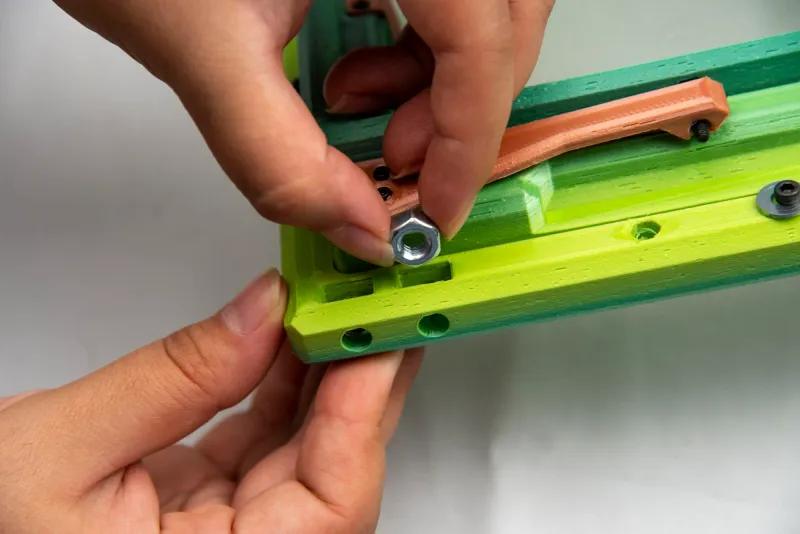
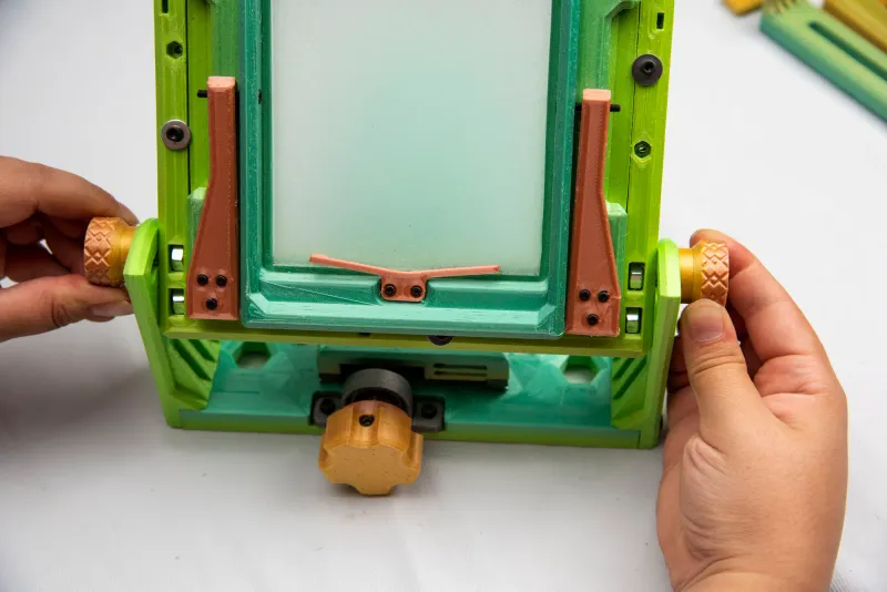
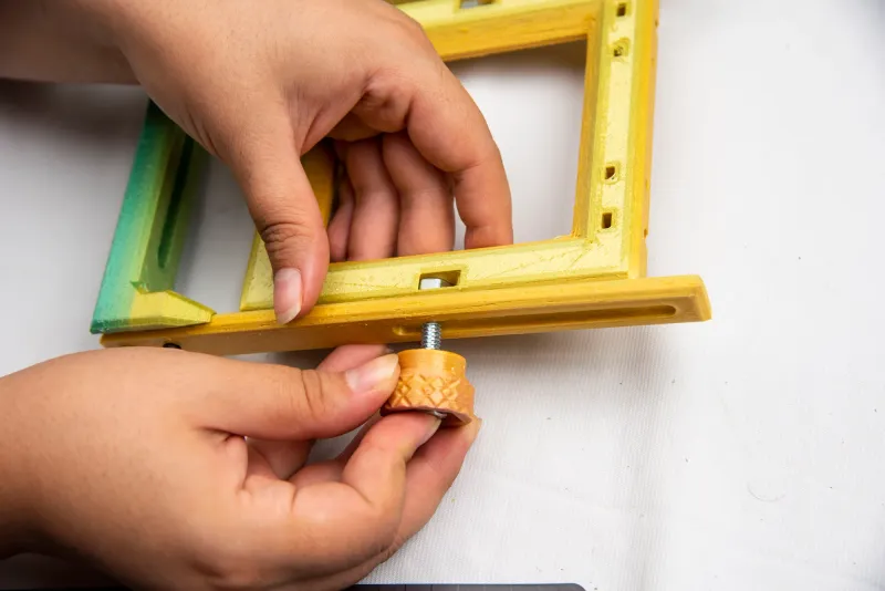
We are now ready to attach our Base to our Rear Frame. To the bottom nut we will attach an Alloy Steel Flat-Tip Set Screws 3/4", 1 on each side.
Next, insert a 1" Steel Hex Head Screws to a Small Side Knob.
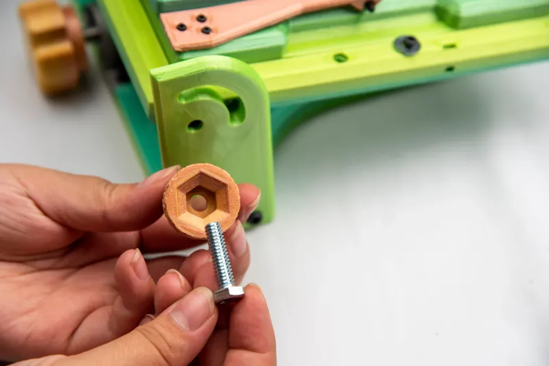
… And attach this Small Knob to the remaining ¼" Alloy Steel Nut.
Repeat on other side.
STEP 14
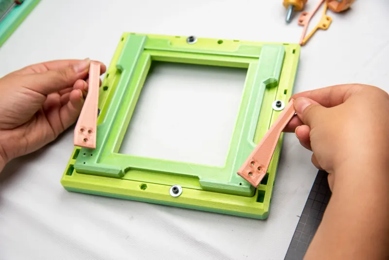
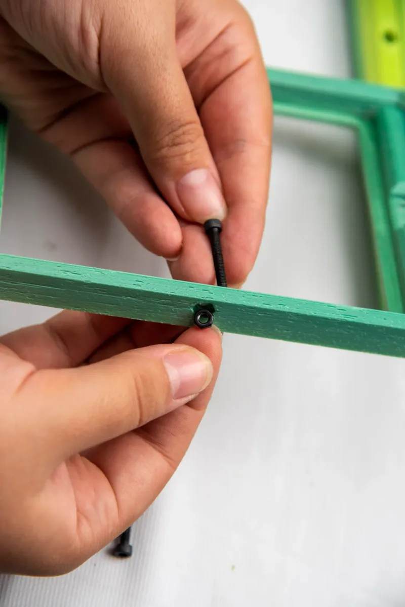
Now we will attach our Side Bars to our Side Bar base.
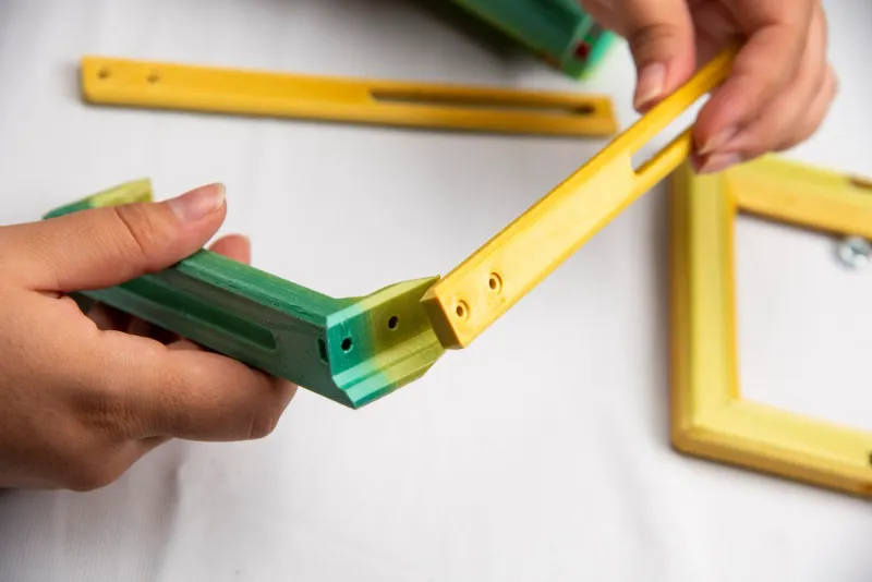
Use two M3 Alloy Steel Socket Head Screws 10mm on each side, and place a M3 Alloy Steel Nut into the slit to secure the screw.
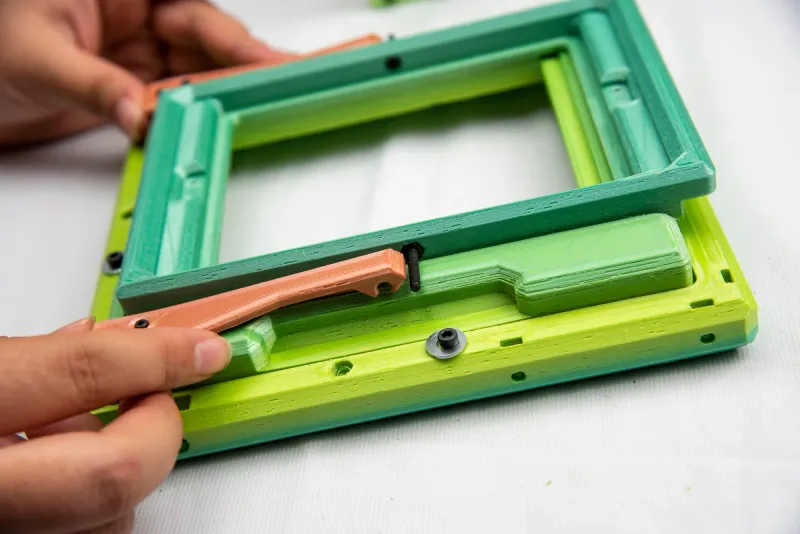
STEP 15
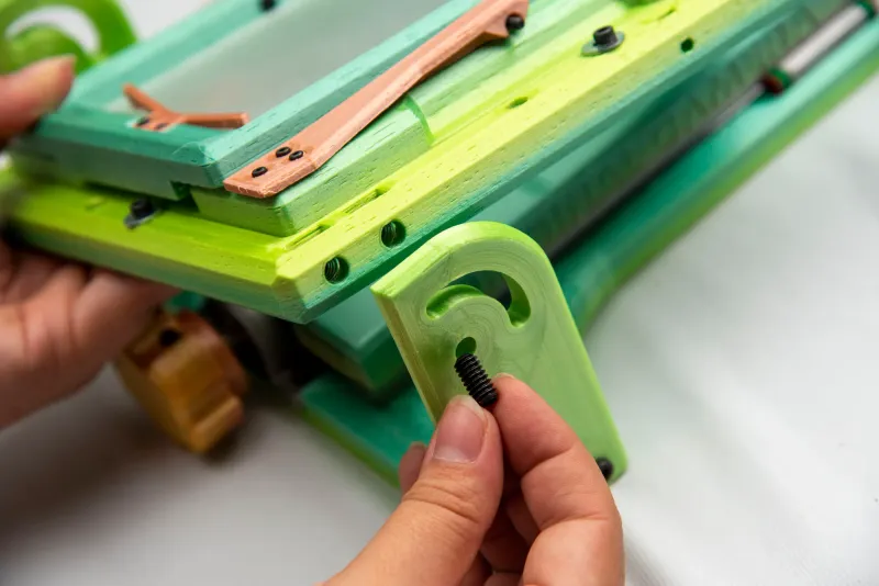
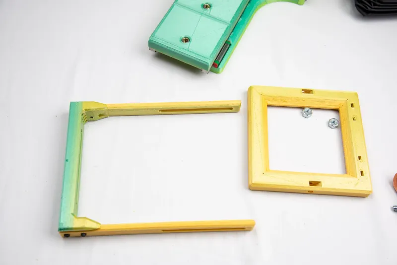
Grab your Front Frame and attach it to your Side Bars and Base. First we'll insert our ¼" Alloy Steel Nuts into the provided slit. There will be one on each side for a total of 2.
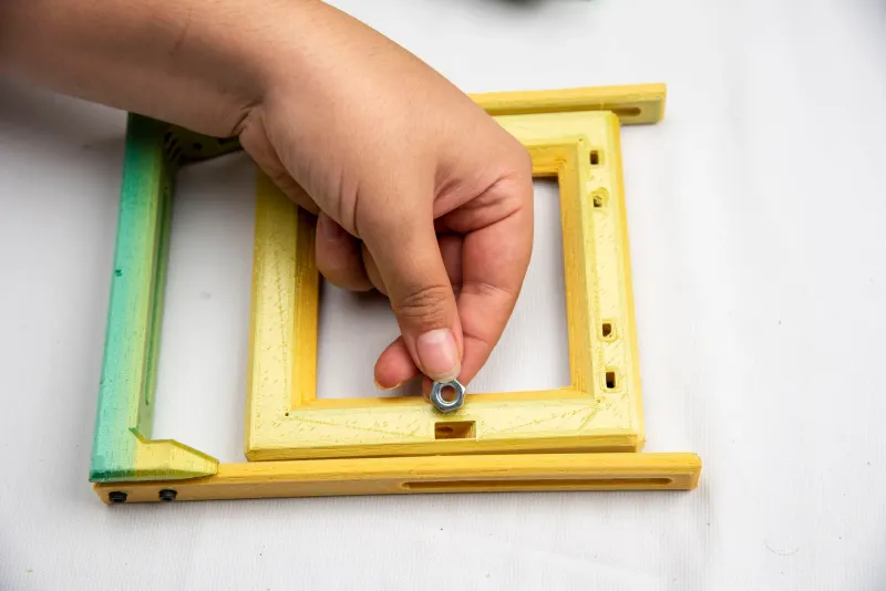
Next, we will insert a 1" Steel Hex Head Screws to a Small Side Knob and attach this Small Knob to the ¼" Alloy Steel Nut. Repeat on other side.
STEP 16
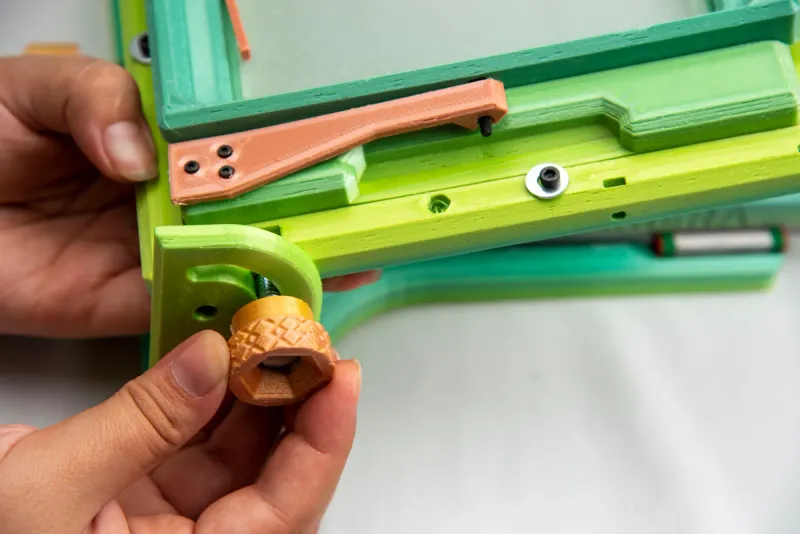
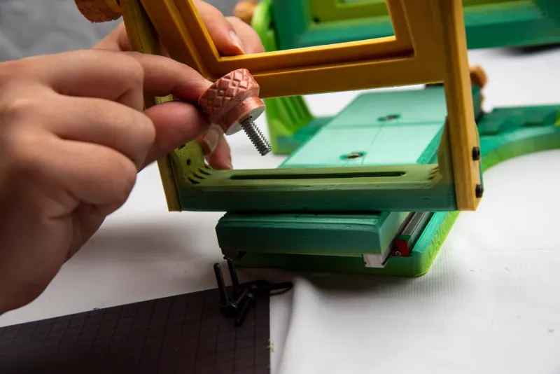
Attach your Front Frame to the Rail base
Insert a 1" Steel Hex Head Screws to a Small Side Knob and screw into the Tapping Inserts for Plastic ¼" previously installed.
STEP 17
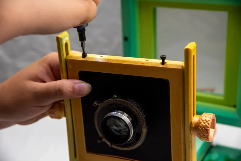
Place 2 M3 Alloy Steel Socket Head Screws 10mm into the openings above the Front Frame, do not screw in yet.
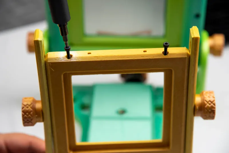
Place Lens Table into Front Frame opening.
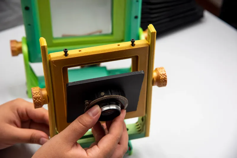
Holding the Lens Table in place, finish attaching the screws.
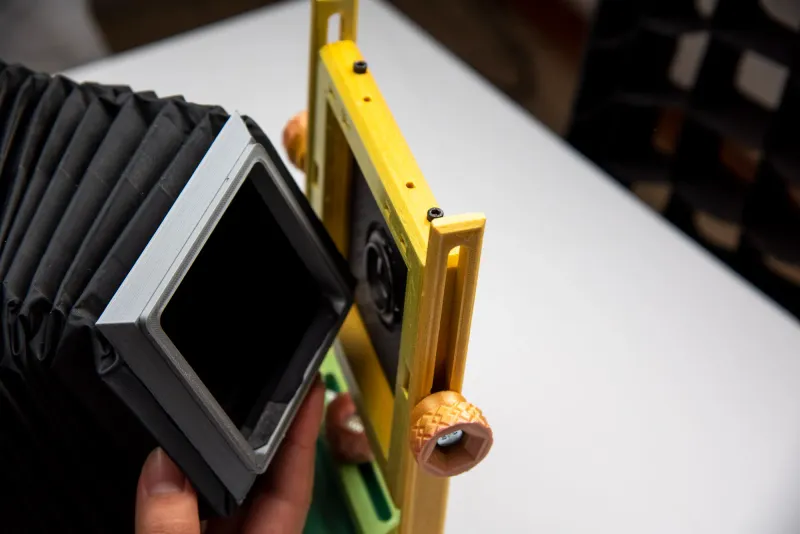
STEP 18
Lastly we will place bellows into our front and rear frame, holding it in place with 8 Phillips screws 5mm. (4 in front, 4 in back)
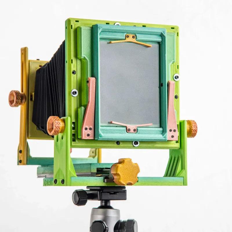
STEP 19
Now you are ready to use your 4x5 camera. Enjoy!
On how to make the bellows, I'll link here a blog that explains the process:
http://salihonbashome.blogspot.com/2015/04/2-some-bellows-basic-concepts-you.html
Tags
Model origin
The author hasn't provided the model origin yet.

