Modular print in place 35mm film scanner

Description
PDFIntroduction
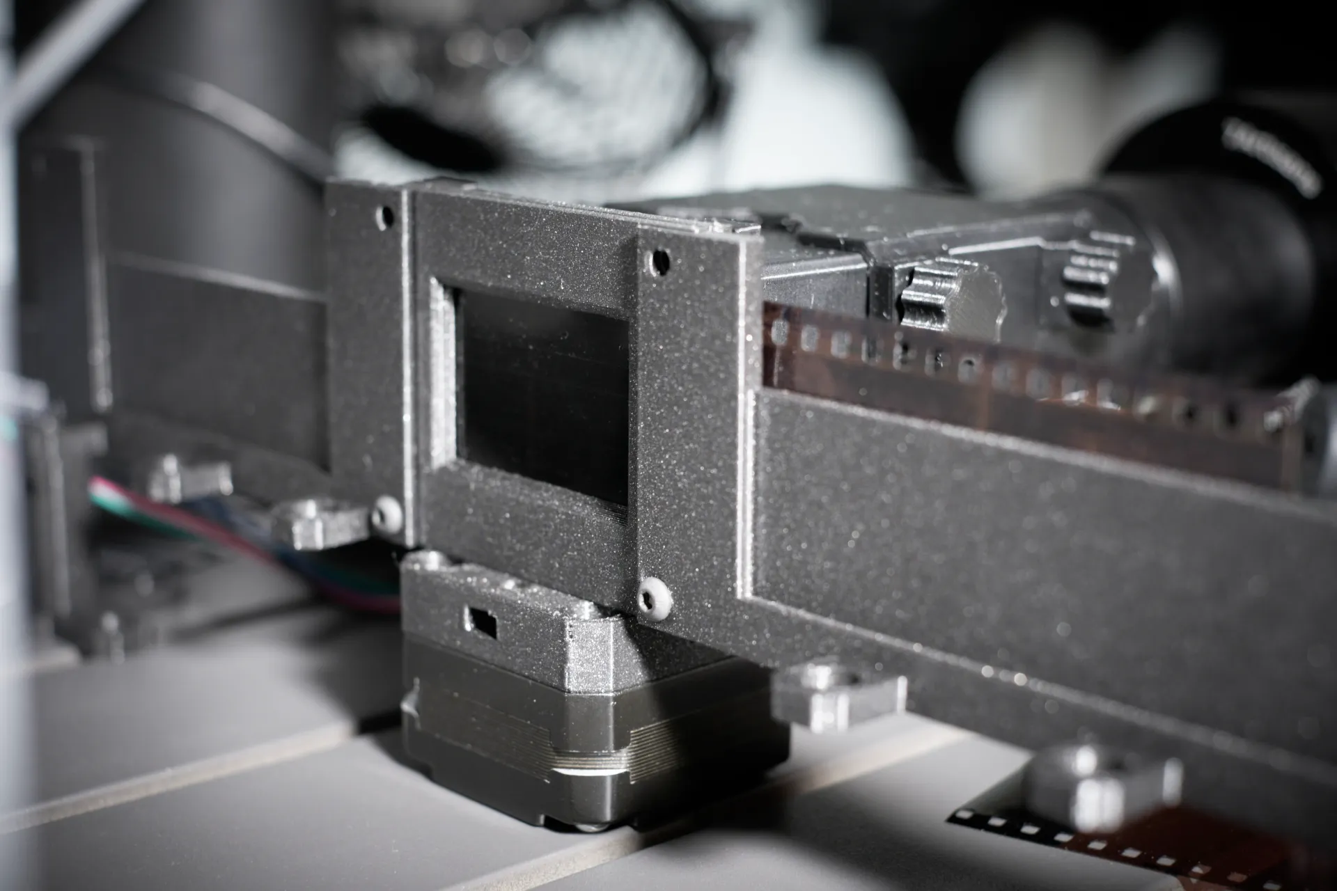
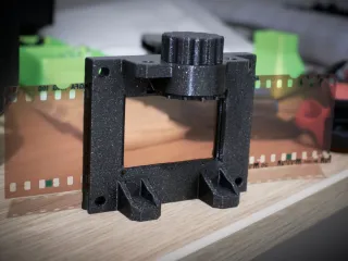
This is a functional print that helps you finally digitize those 35mm film negatives - old family photos and recently developed rolls alike. The main component consists of a frame with a print in place mechanism for advancing the film. The design is modular and open, so you can print (or design) exactly the features you need.
*Lots* of iteration has taken place to make scanning large amounts of film as easy as I could make it - a lot of unexpected film scanning pitfalls were discovered when this project started out as a Lego build back before I had a 3D printer. By now the mechanical Lego parts have turned into fine dust, so a simplified redesign that 3D printing makes possible is long overdue. Printables.com camera contest helped get the motivation to start this CAD project. :-)
Three modes of operation are supported, with increasing levels of convenience but also more equipment needed. Choose one depending on how much film you need to scan:
- Manual: advance the film using a thumbscrew, take pictures of the film using a phone or DSLR.
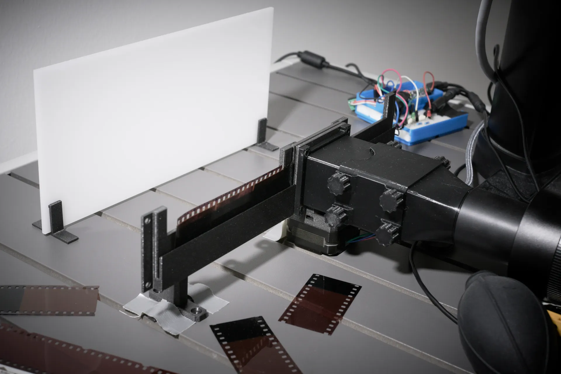
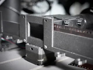
- Motorized: have a stepper motor advance the film, align the first frame using manual controls, then very quickly advance the right number of steps to align the next frame(s).
- Automatic: using some form of video input to the computer (e.g. camera HDMI out via capture card, or USB webcam), run a program that determines the number of steps needed to align the film. Wire up a remote shutter release to have the program automatically scan one whole strip of film at a time.
More background info in writeup here.
Disclaimer
Please be careful with your negatives - this is a 3D printed part and imperfections may cause scratches or tearing. Start out by using empty or otherwise bad film strips when testing, and carefully inspect the film strip before/after, checking for scratches. Also be careful if attaching 3D printed parts to your camera. You're using this model at your own risk etc.
Print settings / orientation
- I recommend slicing with PrusaSlicer 2.5.0 (currently in alpha).
- 0.20mm layer height, 15% infill.
- PLA has worked great for me, try finding a color that has minimal reflectivity.
- Orientation is correct in .stl files
- No supports needed from slicer software, parts needing supports have them already in the .stl file.
Instructions (manual variant):
You will need the following items:
- A high quality camera of some sort, preferably a DSLR or mirrorless camera, but a phone camera might get you good enough results depending on your use case.
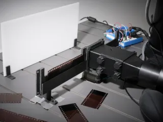
- A bright light source preferably with a high color rendering index, although normal room lighting and a white wall or sheet of paper can work in a pinch.
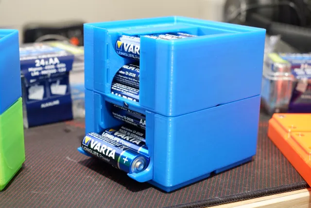
- M3 screws and nuts if you plan on printing any of the optional extra modules.
- A well calibrated 3D printer, tolerances are quite tight on this model (0.2mm)
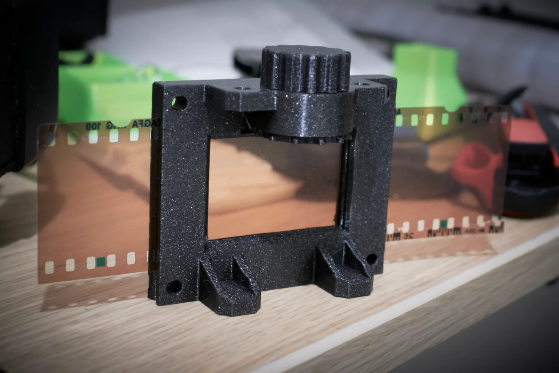
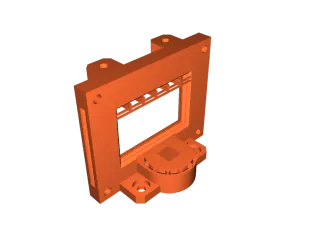
To get started I recommend printing the models in the Frame (required module) folder. With these you can already test the setup and get an idea for what extra modules you may want to print later on.
Tip: If your negatives have some form of paper slip attached to them (see below example photos), a variant of the frame exists with the top part of the frame open (see Misc folder in files section). This makes it possible to scan them directly without first needing to remove the slip of paper, which on older negatives may be very difficult to remove. Note that you cannot use the topmost screw holes in this setup.
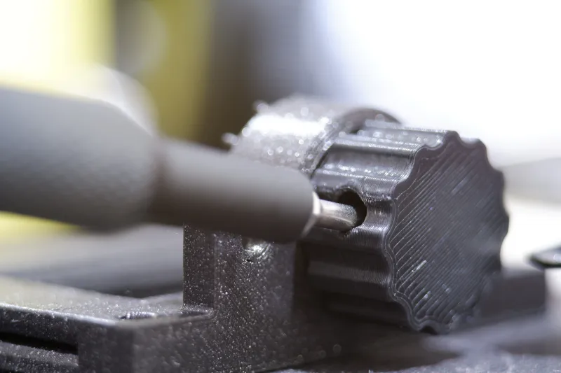
After printing (frame + thumbscrew)
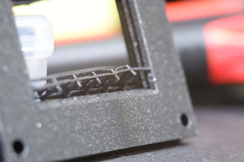
Break loose the print-in-place film advance mechanism by slotting the thumbscrew in it and rotating the thumbscrew back and forth, use a screwdriver for more leverage if needed. If it takes a lot of force your printer may need calibrating (the tolerances are fairly tight at 0.2mm):
Remove the top frame bridging supports by cutting the ends loose along the seam:
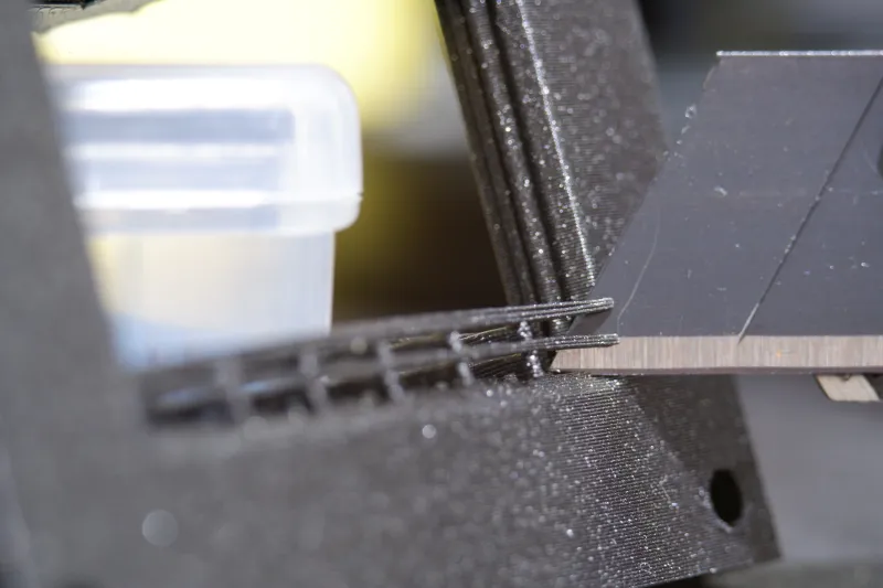
Now you should be able to easily pry out the supports:
Carefully trim edge as needed:
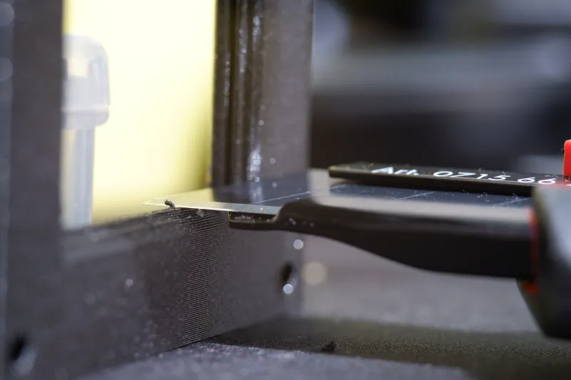
You should be left with very smooth edges around the frame:
Tip: For easier manual scanning, you can mount the frame to something sturdy by placing it upside down (so the thumbscrew faces up) and using the M3 screw holes at the back side of the frame.
Now ensure that your setup works, print any extra modules as needed and start scanning!
Instructions (motorized variants)
First steps are the same as above. In addition, you need to print the Nema 17 adapter + shaft coupler, and attach the adapter to a stepper motor with four M3x8 screws. The frame attaches to the adapter with two M3x8 screws and nuts.
The electronics and programming are out of scope for this submission, but you can find more information on finalizing the motorized and automatic variants here.
Optional extra modules
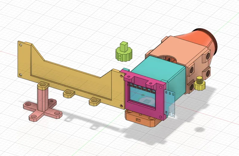
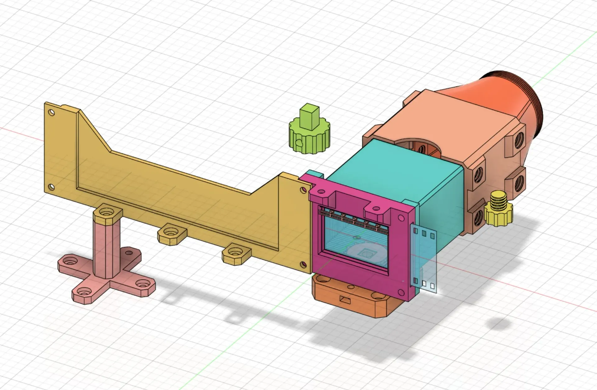
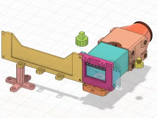
- Negative holder (yellow), including stands (beige) for use with Nema 17 adapter. This can be used for storing film strips to be scanned, and/or collect already scanned film. If you want, you can print two of these and put them on both sides of the frame.
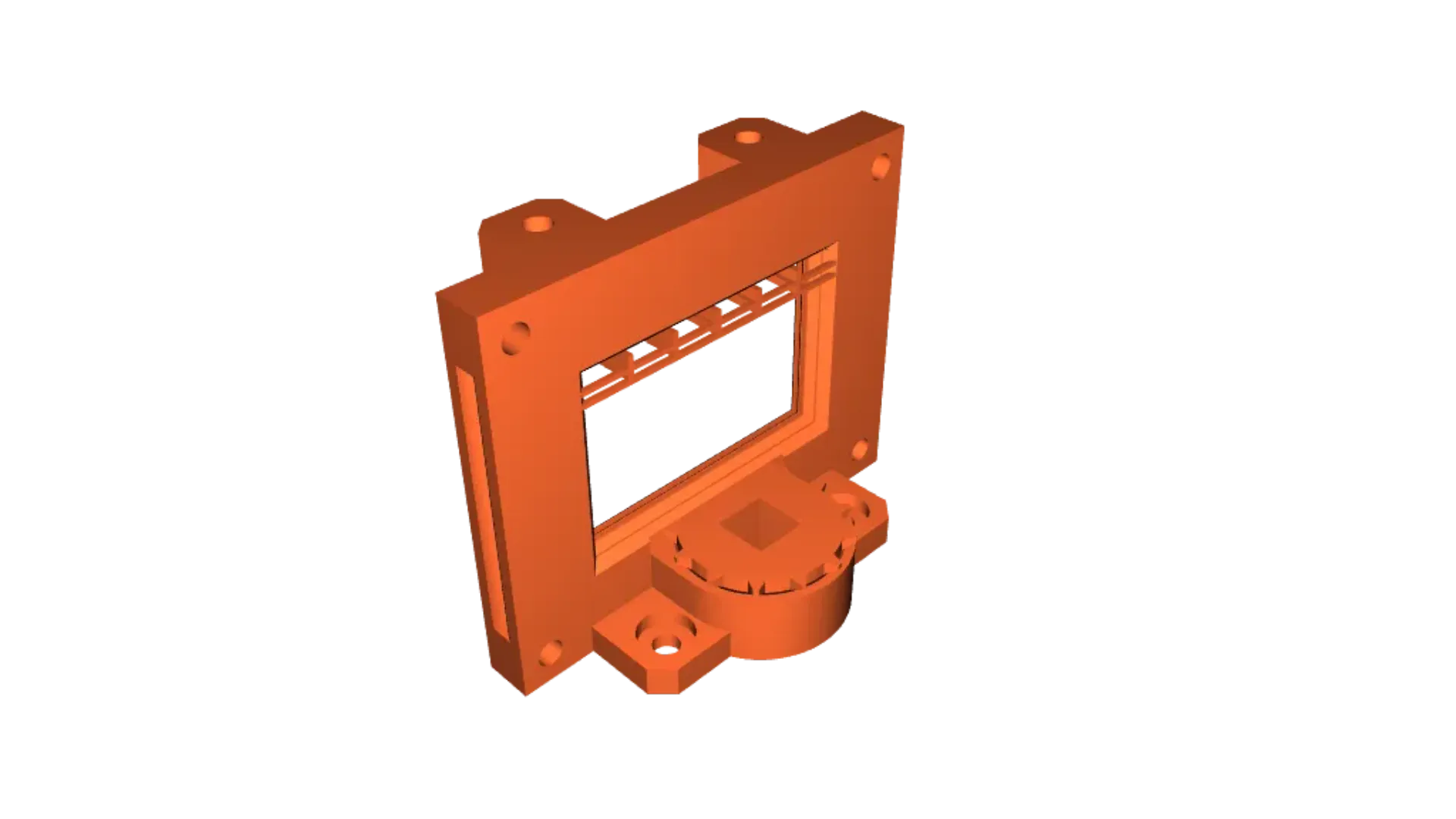
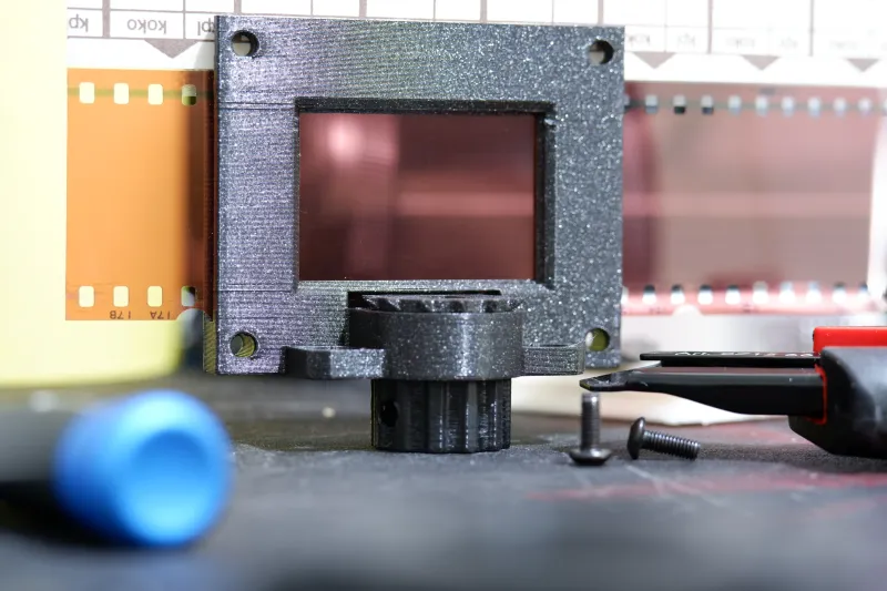
- Nema 17 stepper motor adapter (orange, below the frame) for advancing the film with a stepper motor.
- Lens attachment (cyan) for setting the right focus distance (beige), and securing the frame to your camera lens via its filter thread (red).
The extra modules can be used directly from the print bed with no post processing needed. Just attach them with M3 screws of suitable lengths (M3x8 or M3x12) and nuts.
Tips:
- If you're using a camera with interchangeable lenses, a macro lens will net you the best possible results. Personally I'm using an off brand manual focus macro lens that costs a fraction of my camera manufacturer's lenses with very good results. Another more affordable alternative is to buy (or print!) macro extension tubes, but image quality may suffer.
- Shoot in RAW, use your camera's base ISO (usually lowest possible number), use a high aperture value (around f/8.0), use manual focus, shoot in aperture priority mode and let the camera pick shutter speeds automatically, image size should be set to the native resolution of your camera's sensor (for best quality, and usually has same aspect ratio as the film frames).
- When adjusting focus use a low aperture value, remember to dial it back up before continuing scanning!
- Check your results often, especially in the beginning. You don't want to finish scanning thousands of frames only to find out you've made a mistake and need to start all over.
- Secure the scanner (and camera) to a surface either temporarily with duct tape, or permanently with screws. This is to make sure the camera does not move relative to the frame. You might want to use e.g. plywood for this.
- A light diffuser panel can be useful if you want to point the light source directly at the negative for faster shutter speeds.
Fusion 360 thread files
If you want to modify the threads in the attached Fusion 360 source file, you need to install the following thread files to your Fusion 360 data directory:
- dans98/Fusion-360-FDM-threads (github.com)
- toddmunro/Fusion-360-Lens-Filter-Threads: List of common camera metric threads missing from Autodesk Fusion 360 (github.com)
More information on installing here: Creating custom threads and thread standards in Fusion 360 | Fusion 360 | Autodesk Knowledge Network
Tags
Model origin
The author marked this model as their own original creation.