Room Air Filter
Description
PDFThe room air filter I originally had eventually started to sound like an imbalanced jet engine spinning up to speed (and to pieces). Taking it apart to see what it causing the imbalance, yield very little about the imbalance. However, it became apparent that it was really just a computer fan pulling air across an air filter. Add a circuit board to control power and you had a completed room filter.
This design is based to use minimal support material and is in multiple pieces for ease of printing and to allow printing on a variety of sized machines.
An Arduino uno is used to to generate a PWM single for the fans and to read a Potentiometer to control the fan speed. Two PC fans pull air and an off the shelf air filter completes the package.
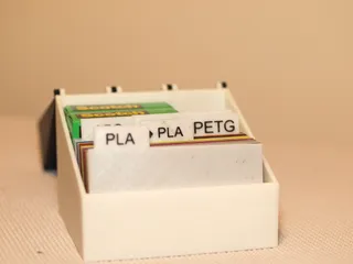
UPDATE: 4/30: Filter has been in use for two months now (mostly with the fans on high) and due for replacing. Uploaded a before (new) and after (used) photo. Filter used was in use for 2 solid months mostly on high for the entire time (running non stop).
Print Settings
Printer Brand:
Prusa
Printer:
I3 MK3S
Rafts:
No
Supports:
Yes
Resolution:
.3mm
Infill:
15-20%
Filament: Push Plastic PLA
Silver
Notes:
Supports are recommended for Part #6 - Middle Center Support. This is just needed for the center area.
A Brim is recommended for the following parts: #2 - Bottom Intake Grill. #4 - Bottom Exhaust Grill, #5 - Middle Intake Grill, & #7 - Middle Exhaust Grill.
Slicer screenshots are provided for recommended orientations. A larger layer height (i.e. .3mm is acceptable to increase speed and reduce time printing).
Print one (1) each of parts #1 - #10 and print four (4) of part #11.
Assembly
Bill of Materials
- Pastic Parts
- 2x - PWM 120mm x 25mm Computer Fan, Static Pressure Optimized
- Air Filter, Holmes Aer1 Compatible. Note: A Honeywell Type H filter is virtually the same size (though not tested with this model) and 3M offers a filter that claims to be compatible with both the Aer1 and Honeywell Type H.
- 36x rare-earth magnets, disk shape, 8 mm diameter, 3mm heigh
- 8x M4 Machine Screws, Cap or Button head, 10-12mm long
- 4x M4 Bolts
- 12v Power Supply
- Barrel Jack (Fitting Power Supply)
- Hookup wire
- Arduino Uno
- Potentiometer
- Knob for potentiometer (Thingiverse has plenty of designs to choose from)
- Perfboard, Breadboard, or Custom Circuit Board for wiring
Electronics Assembly
A PCB design was created for this project and works as an Arduino Shield. However, the wiring is quite simple and does not require a complete PCB/Shield. Using perf board or a breadboard can also accomplish the requisite connections.
Compile and upload the appropriate Arduino sketch. The version I used is included and is basically a simplified version of that created by Matteo Bonora for his server rack mounted fan controller project. (link below)
Install the Potentiometer and Barrel Jack into the base (Part #1) and attach wire to the terminals. Wire the connections according to the included schematic. Fusion Archives with the PCB design is also included if you so desire to make a shield. Arduino and Perf or Bread board can be adhesive to the inside of the Base. Avoid blocking any of the holes in the base. Assembly video is included and begins with the electronics layout in the base.
Plastic Part Assembly
Remove any brim and support materials. Clean off any elephant foots. Install magnets into the square holes with super glue. Mind the polarity of the magnets and the part orientation.
Begin with installing the base and bottom center support (parts 1 & 3). Use 4x M4 machine screws and 4x M4 Bolts. The Middle Center Support (Part # 6) and Top Center Support (Part #9) just slip fit in. Mont the 2 PC fans with their included hardware. mind the air flow direction of the fan Fans go on the exhaust side. Fan screws need to be fed through the intake side and into the fans. The fans also double as structural support for the fan.
Once the fans are install the filter can be installed. Rubber seal goes towards the center of the assembly. Four filter locking tabs hold the filter down. 4 M4 machine screws thread into the center support pieces to keep everything secure.
Finally, attached the six grill pieces (# 2, 4, 5, 7, 8, & 10) from bottom up. These just attach with the magnets and can be easily removed for cleaning/dusting, filter replacement, or fan replacement/care.
Final Thoughts
Warnings
The current designed grill grates help minimize contact with the fans but currently are still big enough to fit an adult finger through and reach the fan blade. Use caution, especially when/where children could come into contact with it.
As with any electronics project, exercise caution to avoid issues such as electrocution or fire. Use at your own risk.
Links
Assembly Video: https://youtu.be/jHkEppTdztg
Matteo Bonora's server rack mounted fan controller project: https://www.instructables.com/id/Temperature-Control-With-Arduino-and-PWM-Fans
Fans used in Testing: https://smile.amazon.com/dp/B07CG2PGY6
Aer1 Filters (Aftermarket/3rd Party used in prototype): https://smile.amazon.com/dp/B07F81MGRZ
Honeywell Filter (not tested but virtually the same size): https://smile.amazon.com/dp/B004EERH36
3M Filtrete Filter (Reported to fit both the Aer1 and Honeywell Type H): https://smile.amazon.com/dp/B07NBK1NTZ
Rare Earth Magnets (ones used no longer on amazon, This is the current Amazon's Choice one): https://simle.amazon.com/dp/B075TJNQQH
Power Supply (This one is overkill for this project but gave good results in other projects I've done): https://smile.amazon.com/dp//B01461MOGQ
Barrel Jack: https://smile.amazon.com/dp/B01M1D5GIP
PCB Manufacture I used: https://jlcpcb.com/
Category: Household SuppliesTags
Model origin
The author marked this model as their own original creation. Imported from Thingiverse.


