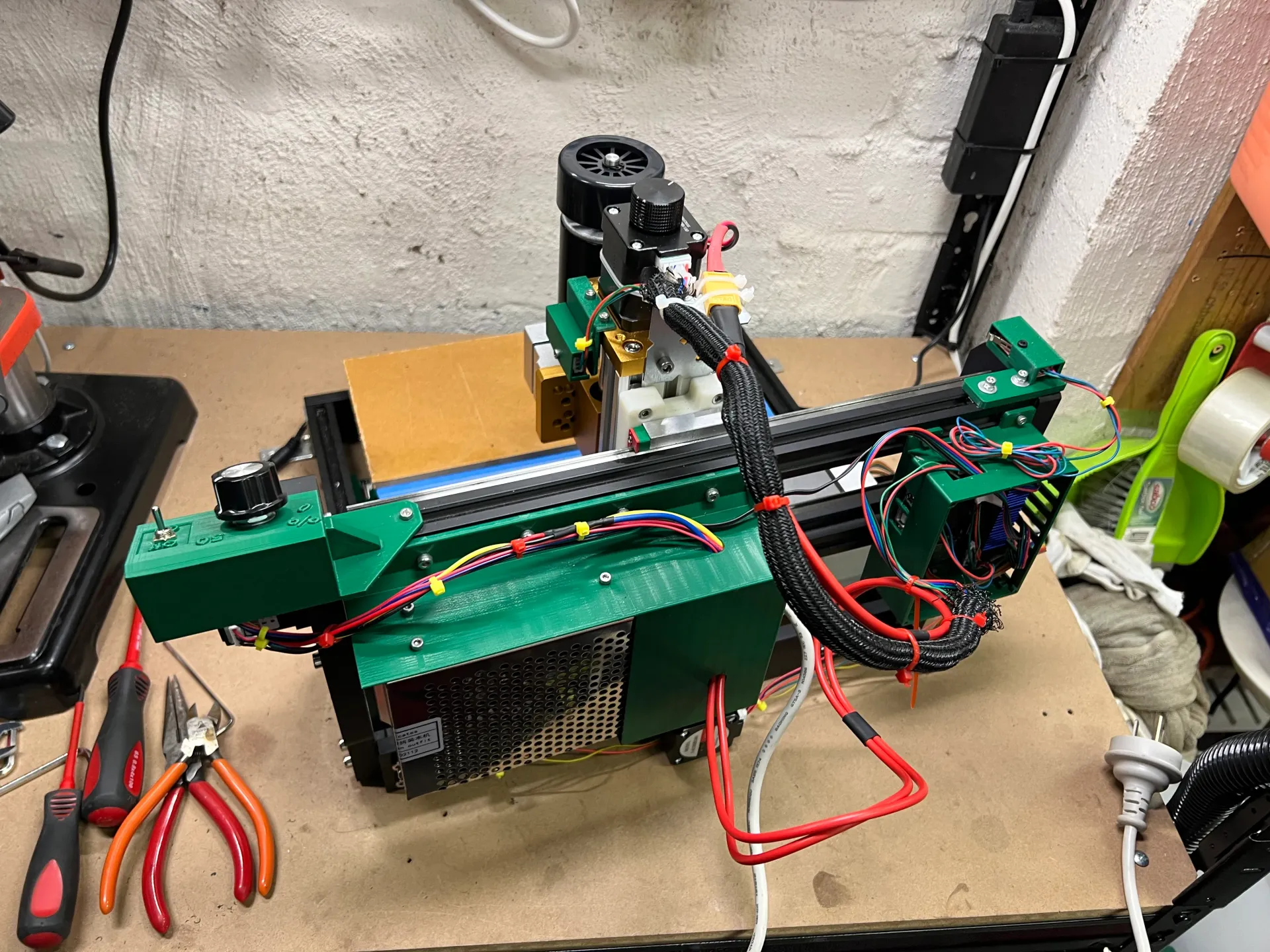
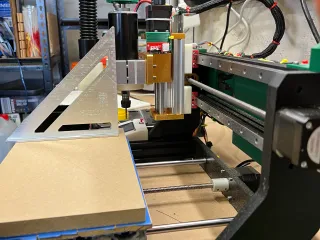
3018 CNC - Ultimate X-Axis Upgrade using MGN15H Linear Rails and a High Power Spindle


Description
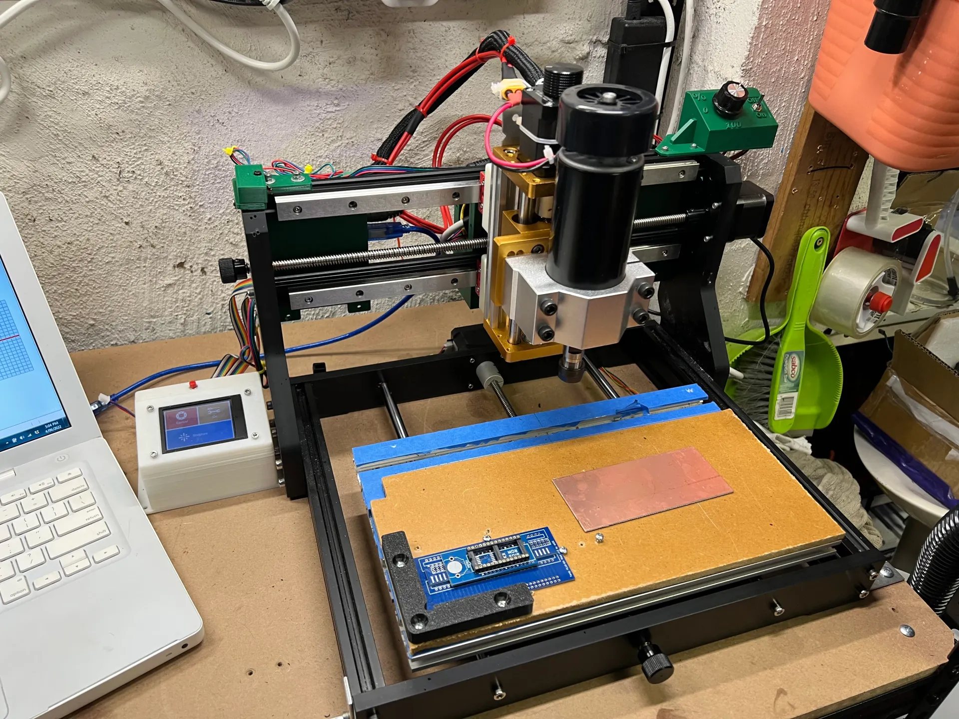
PDFThis Upgrade gives you the Ultimate 3018 CNC Machine - PCB's and Aluminium can now be milled accurately.
Build Steps:
- Remove the old X-axis rods and Z-axis carriage
- Loosen the vertical X-axis mounts and slide them as far rear as they'll go, tighten the bolts (this minimises Y-axis area loss)
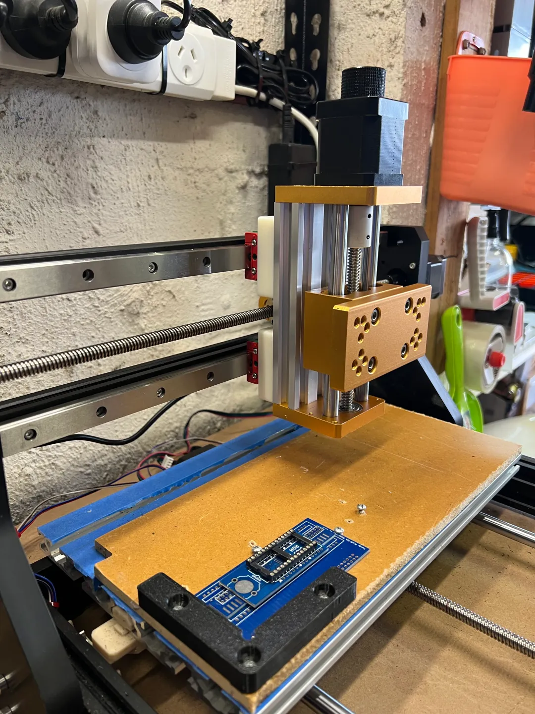
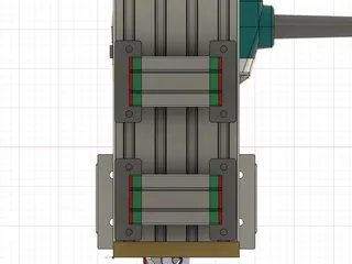
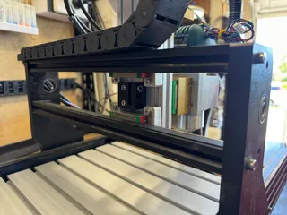
- Install the Linear Rails using fixed M3 T-nuts (not the rotating ones which have a habit of not engaging correctly). You only need to secure every second mount point.
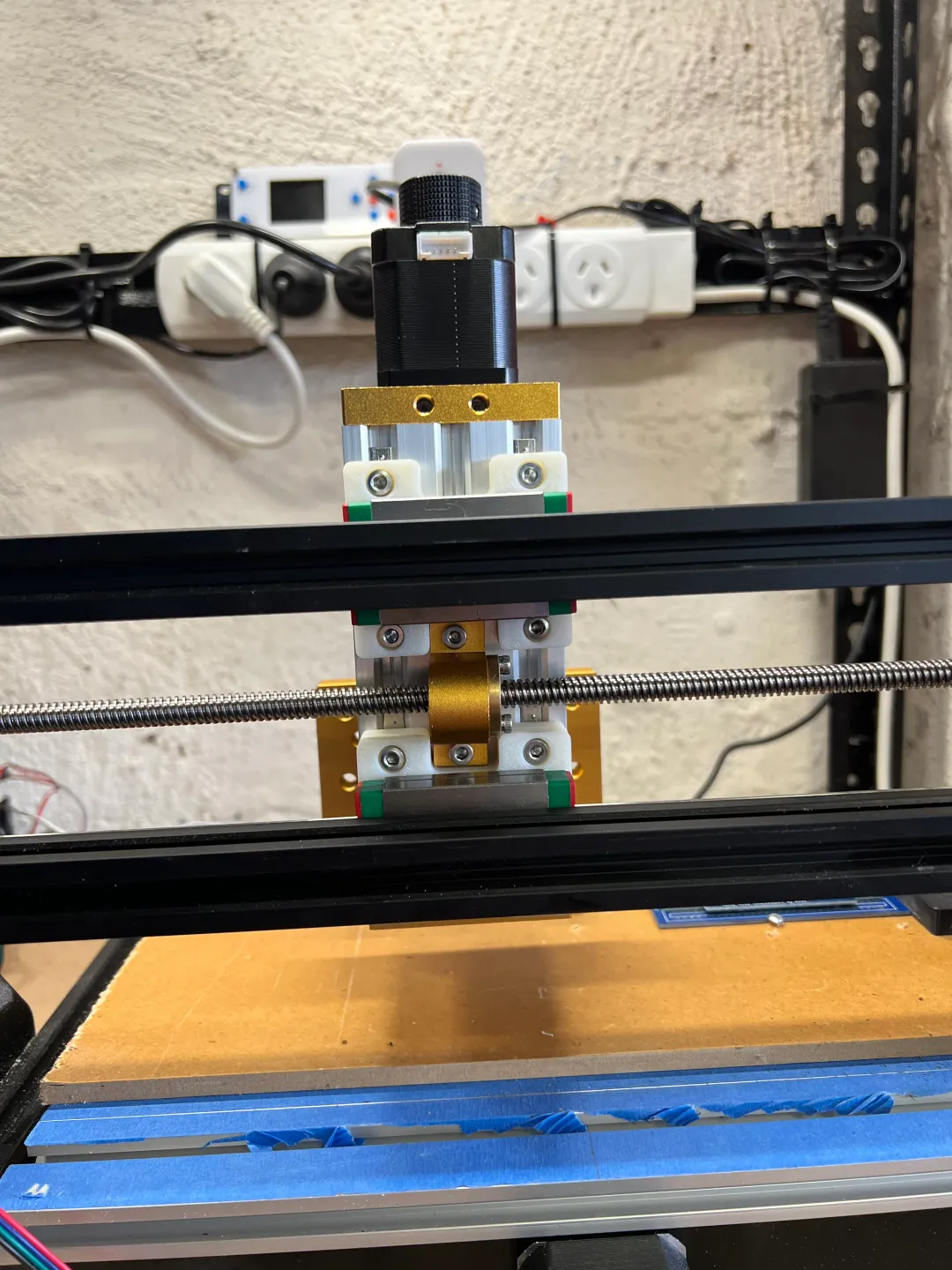
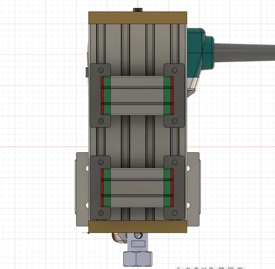
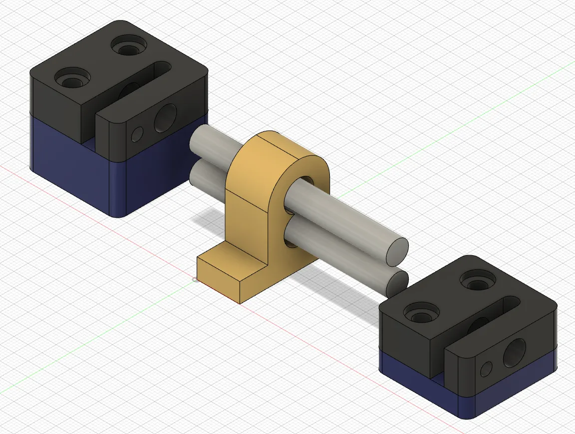
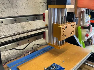
- Install the MGN15H Mounts to the Carriages using M3 Bolts
- Install the Z-axis Upgrade loosely to the included T-nuts using M4 Bolts - this can be a bit fiddly to get right so be patient. I start with the top mount, then bolt on the bottom mount and leave the lead-screw mount to last (I use a thick piece of wire to push the T-nuts up into place).
- Once all the Z-axis bolts are hooked up, tighten up the 2 main mounts while ensuring they are parallel with each other and the X-axis runs freely from side to side.
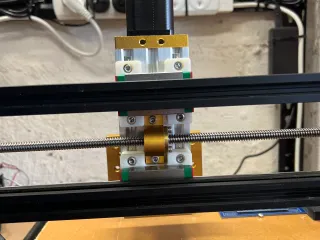
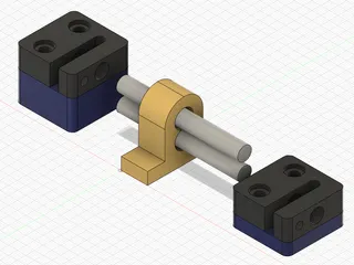
- Install the X-axis lead screw and anti-backlash system - tighten up the lead screw coupler and then make sure it moves the X-axis cleanly before tightening up the lead-screw mount bolts on the back of the z-carriage.
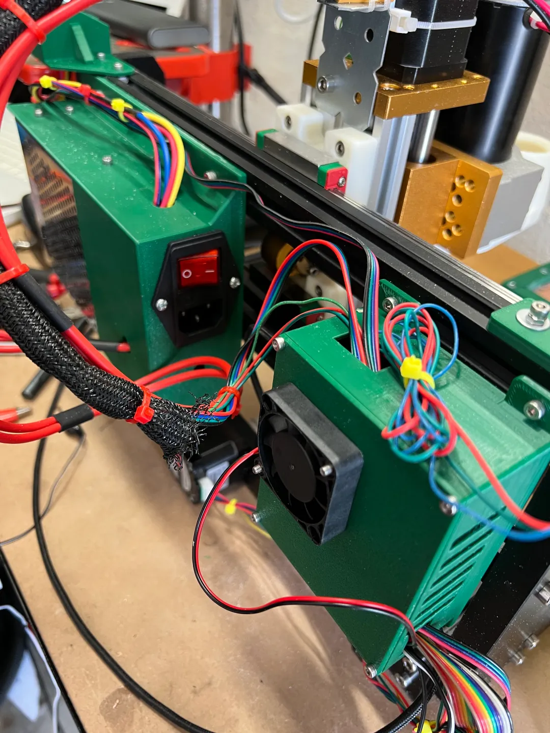
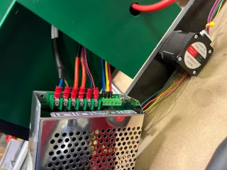
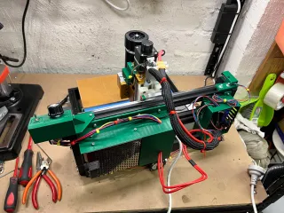
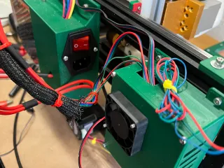
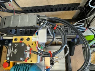
- Install your wiring and Power supply as desired.
- Install your end-stops and configure them as required.
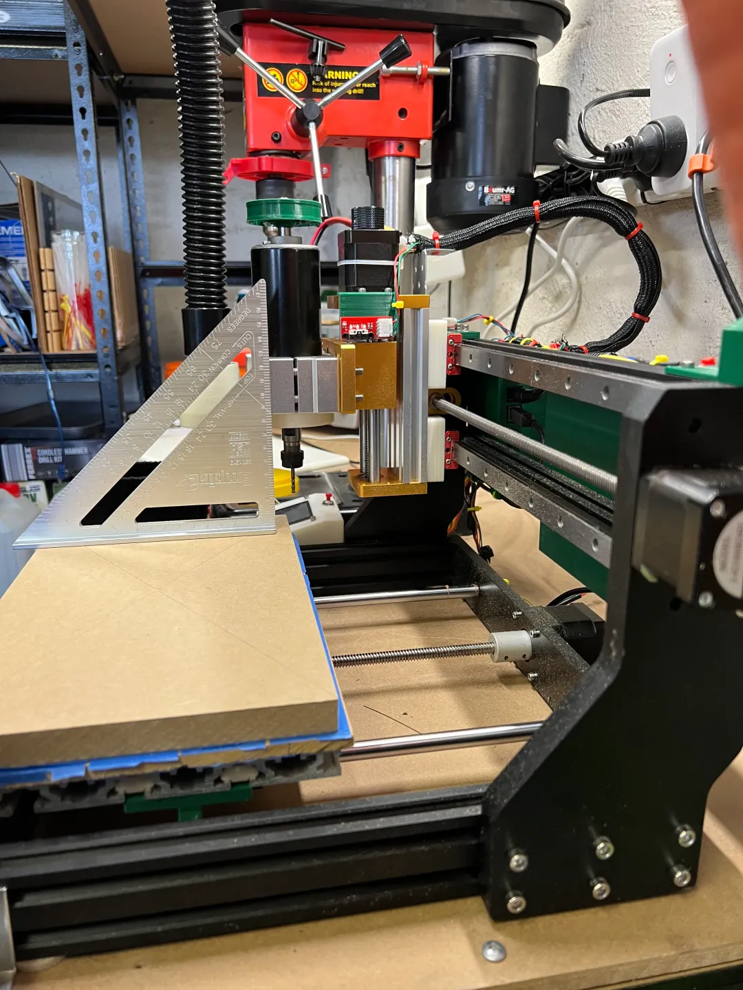
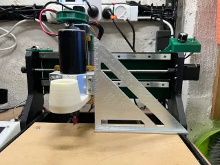
Tramming the Spindle:
Thankfully my design makes it super easy.
X-Axis: You just need to put a bit into the collet and drop the bit down to the bed. Then just spin the machine around and loosen all the screws for the z-mounts (including the lead screw block).
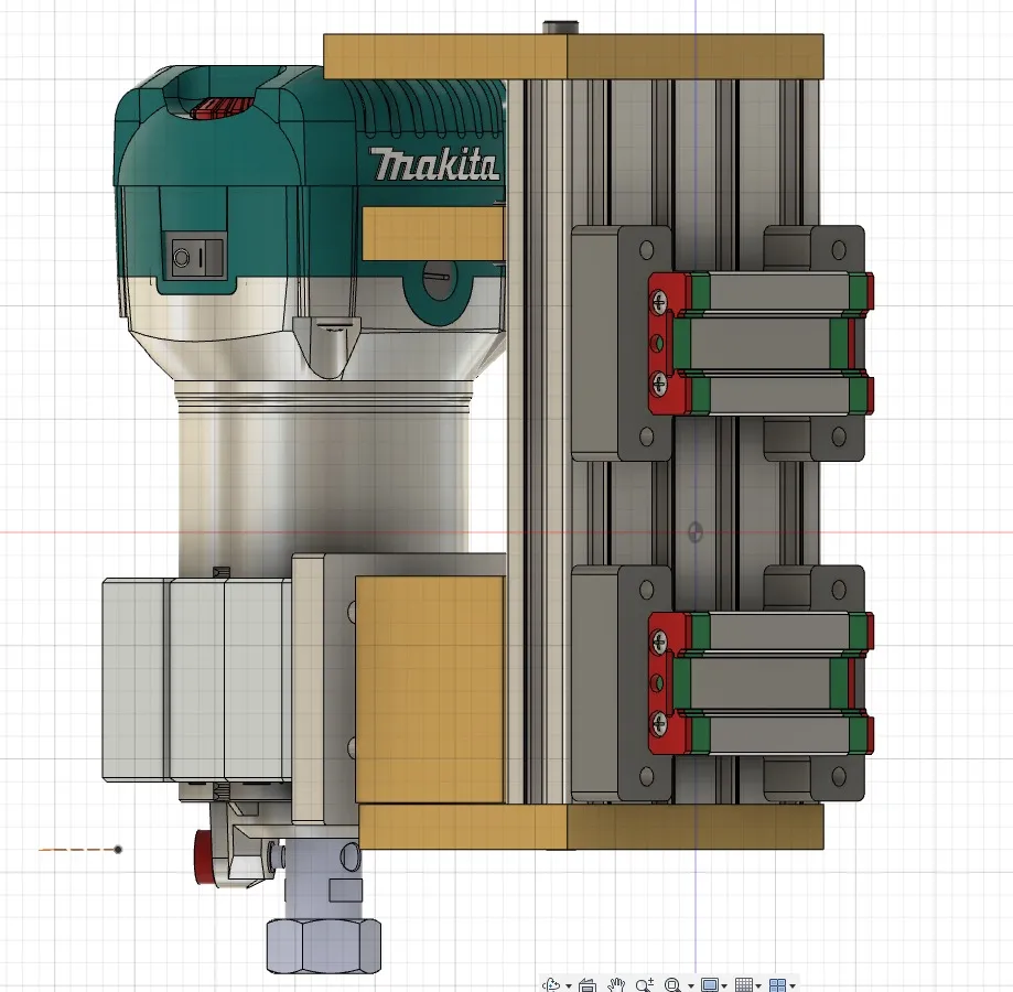
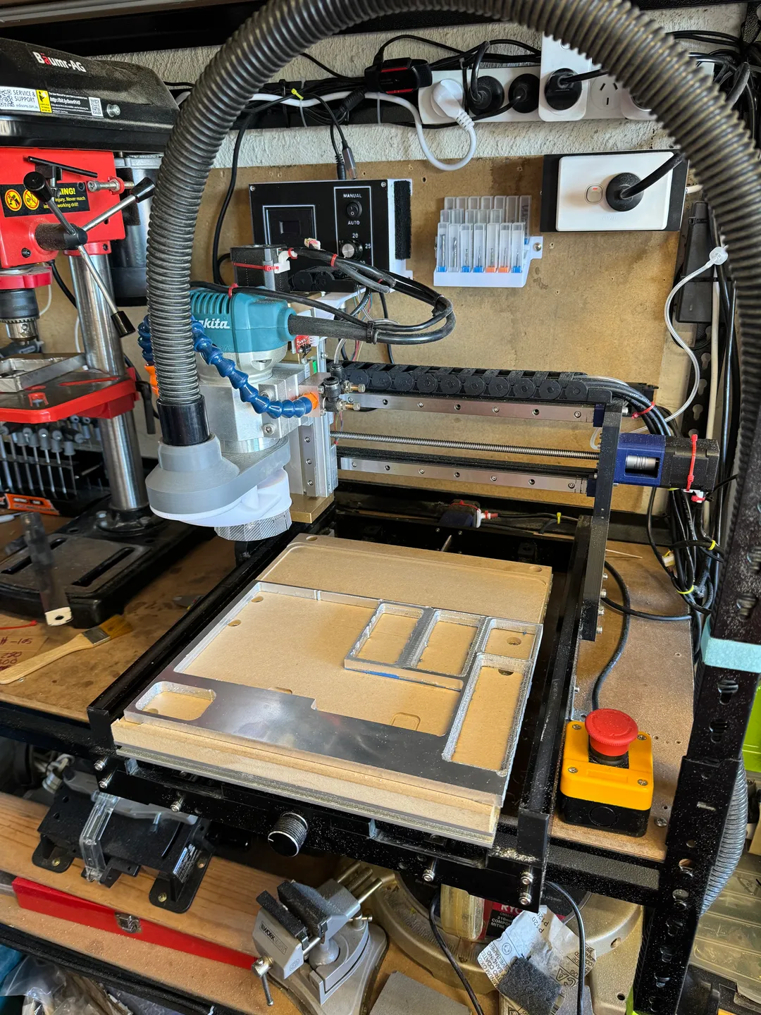
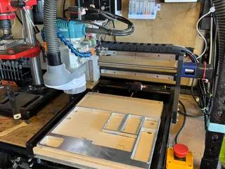
Then use a builders square to ensure the actual Spindle mount (not the Z-frame) is square with the bed and tighten up the bolts (ignore the test spoil board in the photo, I put it back on after tramming the spindle).
Y-Axis: The procedure is basically the same, but this time you loosen the bolts attaching the X axis to the base. Then set the builders square against the front of the spindle mount. Adjust till its Parallel with the bed and then tighten the bolts back up.
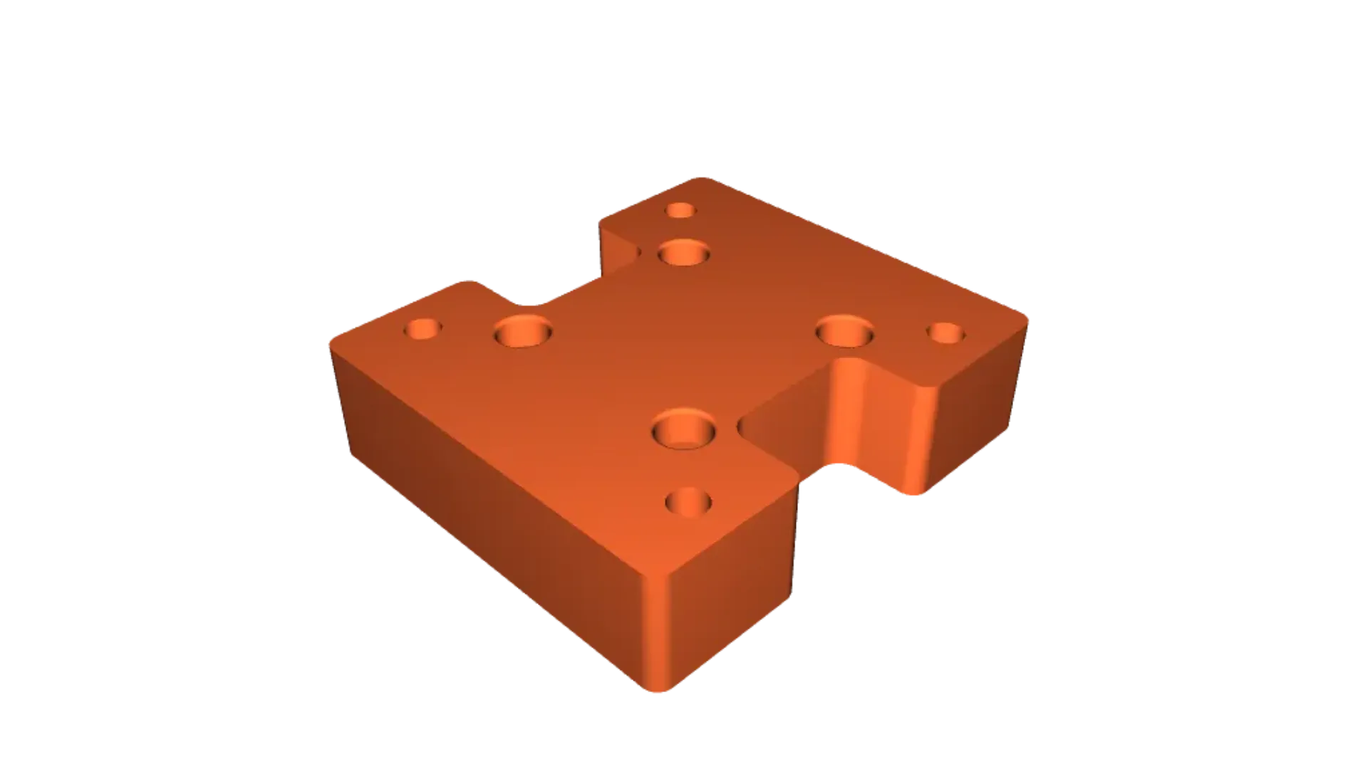
Printed Parts:
- MGN15H Mounts - Print in ABS+ or other structural Plastic
- Power Supply Mount
- End-stop mounts x3
- Y End-stop Bump
- Spindle Speed Controller Panel
Purchased Parts:
- Z -Axis Upgrade
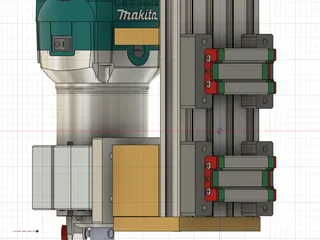
- or Z-Axis Upgrade w/ Ballscrew and Linear Rails (this Z-axis is higher quality and will support using heavy spindles like the Makita 700 series router)
- 2x 300mm Linear Rails w/ 1x MGN15H Carriage
- 500watt Spindle, Mount and Power Supply
- Fused IEC Socket for Power Supply
- Spring loaded M3 T-Nuts
- 3x MakerBot v3 Limit Switches / End-stops
Optional Parts:
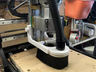
- Dust Shoe for the 500w Spindle
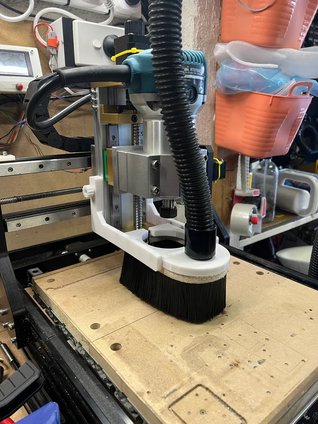
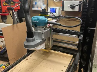
- Dust Shoe for Makita Router Spindle
- Mount for 15mm x 30mm Cable chain
- MKS DLC32 Controller and TS24 LCD Screen
- Screen Mount for the TS24 LCD
- Rear CNC Mount and Case for the MKS DLC32
- Replacement fan for the 500w Spindle
- Cable Guides for 2040 V-Slot Extrusions
- 3040 Pro Bed Upgrade
UPDATE:
I've added support for adjustable anti-backlash blocks as used by RatRig and OpenBuilds. These only fit between the mounting blocks of the Ball-screw Z-Axis. These provide for much higher accuracy than the spring type anti-backlash nuts used on 3D printers.
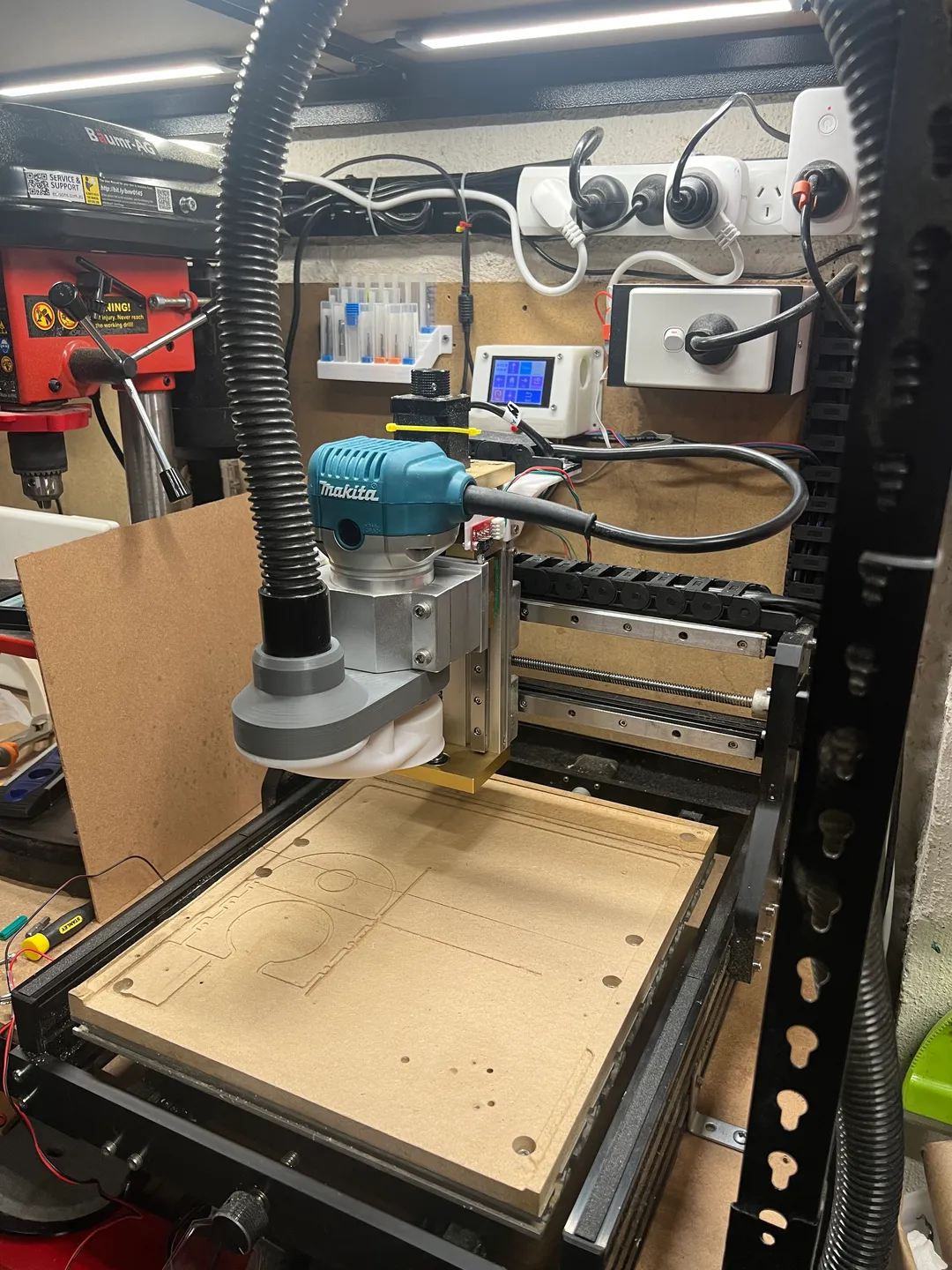
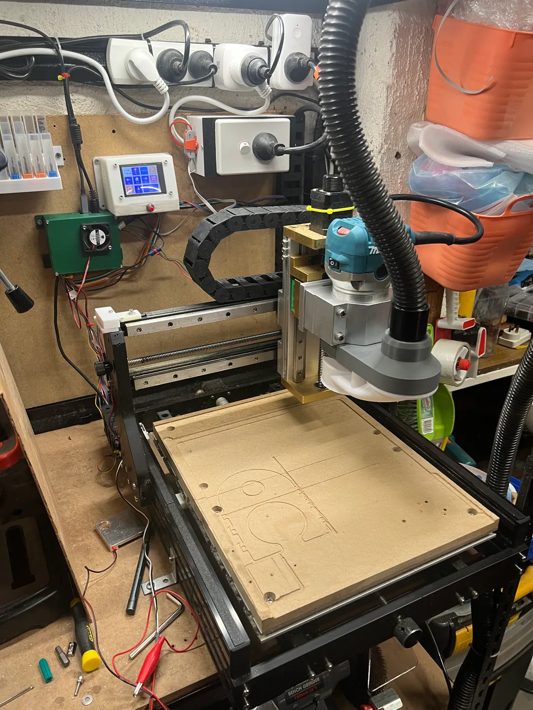
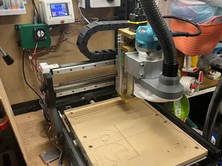
and here it is in action:
Ballscrew Z axis with Makita spindle:
Tags
Model origin
The author marked this model as their own original creation.


