X, Y and Z calibration tool for IDEX / dual extruder / dual color 3D printers

Description
PDFRemix of the amazing design of Lmaker.
Added a part to be able to compare/finetune the Z-axis (offset) as well.
This is a 10-15min print to make life easier when calibrating the X, Y, and Z-axis of (independent) dual extruder 3D printers.
Instructions;
X and Y offset calibration;
Step one;
Print "Test_idex_X_Y_Z_E1" with the first extruder
and print “Test_idex_X_Y_Z_E2” with the second extruder
Step two;
Look for the first outside lines (E2) in X and Y directions that align perfectly with the inner lines (E1). This is the amount that the 2nd extruder needs to be higher or lower than the current offset value.

Each line indicates a 0.1mm offset, and the + and - icons indicate if the offset of the 2nd extruder needs to be added or subtracted.
Example 1
In this example extruder 2 is perfectly aligned with extruder 1 in the X and Y axis, this is the result you want to achieve.

Example 2
In this example, the 3rd line on the minus side for Y, and the 4th line on the minus side for X are the first to align.
This means that the offset of E2 needs to be -0.3mm in X and -0.2mm in Y.
(for example; X460, Y0 → X459.7, Y-0.2)

Example 3
In this example, the 3rd line on the minus side for Y, and the 7th line on the plus side for X are the first to align.
This means that the offset of E2 needs to be +0.6mm in X and -0.2mm in Y.
(for example; X460, Y0 → X460.6, Y-0.2)

Z (offset) calibration;
Total Z offset / babystep / first layer height;
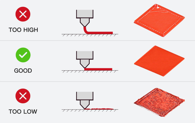
First you can make out from the E1 side if the first layer height is good on this part of the bed.
The lines in this section should be perfectly aligned. This means that there should be no gaps in between the lines (gap too big), and no raised lines either (gap too small).
If you see gaps between lines; "Raise the bed on every corner for an equal amount" or “Decrease first layer height / babystep / total Z-offset / Bed Z value by 0,05mm increments in firmware”
If you see raised edges/lines; "Lower the bed on every corner for an equal amount" or “Increase first layer height / babystep / total Z-offset / Bed Z value by 0,05mm increments in firmware”
2nd extruder Z offset;
Next, you can calibrate the Z offset of the 2nd nozzle compared to the 1st extruder.
You can do this by comparing the E1 and E2 sections in the middle.
The E1 section should be perfectly calibrated as explained above. The goal is for the 2nd side to look the exact same.
If E1 is good, E2 shows gaps; Decrease 2nd nozzle offset value by -0,05mm increments in firmware.
If E1 is good, E2 shows raised edges/lines; Increase 2nd nozzle offset value by +0,05mm increments in firmware.
More info on how first layers should look can be found here;
First Layer Calibration (i3) | Prusa Knowledge Base (prusa3d.com)
Tip;
I recommend printing this file multiple times after each other to verify the offsets and changes you made. If you printed a couple; I recommend labeling them with a sharpie or pen.
Changelog;
17-05-2022: Rotated the .stl files so you don't have to :)
Tags
Model origin
The author remixed this model.

Differences of the remix compared to the original
Added Z-offset functionality


