Bionic PSU Brace for Prusa I3 MK3 / MK3s
Description
PDFAnyone who builds an enclosure should remove the PSU from the printer and place it outside. Prusa supplies a brace model that is supposed to stiffen up the frame when you remove the PSU. I did not like that design very much, as it only uses the mounting points of the original PSU, and so I made my own.
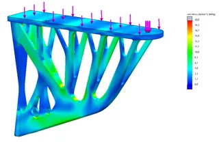
I happen to be playing around with topology optimization software right now, and so I ran a few loops and approximated what the topology optimization showed. The screenshot is from an older version where I used three mounting points, only to realize that the middle one is indeed pretty useless.
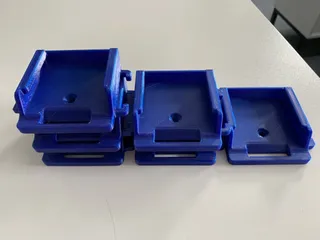
Print 1x brace, 2x Clampnut
You will need some additional hardware: 2x M4 hex nuts, 2x M4x15 bolts (flat head preferably). Use the original PSU mounting hardware for the top holes. Also 2x M3 hex nuts to insert into the clamp nuts, and M3x20 bolts (I used leftovers from my Prusa build). Washers underneath the bolts are advisable, to distribute the pressure better to the printed material, if you use a thicker washer you may need M3x25.
Print Settings
Printer Brand:
Prusa
Printer:
I3 MK3S
Rafts:
No
Supports:
No
Resolution:
0.2 mm
Infill:
3ß%
Filament:
Generic PETG
Notes:
Use 3D honeycomb for best all-around stiffness distribution. I printed 3 shells, more is better.
How I Designed This ===================Design work in SolidWorks 2019, with the integrated topology optimization (TOSCA). Optimization goal was for best stiffness to weight.
Using the side of the aluminum profile for load transfer gives the biggest gain, since the loads are then running in a fairly straight line, whereas the original brace has an unsupported 90° bend which isn't very good for stiffness.
Is this complete overkill? Oh yes it is. But it's also very neat and was a lot of fun to do.
Category: 3D Printer AccessoriesTags
Model origin
The author marked this model as their own original creation. Imported from Thingiverse.


