Proxxon MF70 CNC kit
Proxxon MF70 CNC kit The Proxxon MF70 milling aluminum:https://www.youtube.com/watch?v=0W1iQ1PUNVY Following…
34
166
0
2414
updated May 2, 2022
Description
PDFProxxon MF70 CNC kit
The Proxxon MF70 milling aluminum: https://www.youtube.com/watch?v=0W1iQ1PUNVY
Following improvements/changes have been made compared to the design of ttsalo:
- full x-axis table range is now available. Using the ttsalo design I lost 5 mm of the x-axis range; perhaps this issue was caused by changes Proxxon did make to the design of the MF70.
- No bearings need to be removed/replaced; the x/y/z axis is simply driven by a coupler connecting the stepper directly to the handwheel. The coupler is slightly flexible since it is made out of NinjaTek.
- holes for end switches have been added for all axis
Required 3D printed parts:
- BracketX.stl (1x)
- BracketY.stl (1x)
- BracketZ.stl (1x)
- CouplerXY.stl (2x)
- CouplerZ.stl (1x)
Optional 3D printed parts:
- ShockAbsorber.stl (3x)
- DirtCapBracketX (1x)
- DirtCapBracketY (1x)
Required other parts:
- Nema17 (3x)
- hex screw m3x16 (15x)
- grubscrew m3 (6x)
- nut m3 (6x)
- hex screw m3x25 (4x) or diameter 3 mm screws that 8 mm longer than the originals (4x)
- hex screw m3x30 (4x)
- washer m3 (4x)
Optional other parts:
- endswitch for x-axis and y-axis (2x)
- screw m2.5x20 (4x)
- nut m2.5 (4x)
- endswitch for z-axis (1x)
- screw diameter 2.5 mm, length 15 mm (2x)
Suggested Materials:
- ABS (95% infill): BracketX, BracketY, BracketZ
- NinjaTek Cheetah (50% infill): CouplerXY, CouplerZ, DirtCapBracketX, DirtCapBracketY
- NinjaFlex (20% infill, not important): ShockAbsorber
- no supports are required
Assembly instructions x and y-axis:
- attach steppermotor to bracketX(Y) and shockabsorber using hex screw m3x16 (4x)
- assemble couplerXY using 2 grubscrews and 2 m3 nuts
- attach couplerXY to handwheel using hex screw m3x16 (of course the handle from the handwheel needs to be removed first).
- attach bracketX(Y) to x/y table using hex screw m3x25 (2x), (or use the longer screws with diameter 3 mm if they could be resourced)
Assembly instructions z-axis:
- attach steppermotor to bracketZ and shockabsorber using hex screw m3x16 (4x)
- assemble couplerZ using 2 grubscrews and 2 m3 nuts
- attach couplerZ to handwheel using hex screw m3x16 (of course the handle from the handwheel needs to be removed first).
- attach bracketZ to z-column using hex screw m3x30 (4x)
remark:
- I did tap M3 thread in the table for the X/Y axis since I could not source screws with the same pitch that were originally holding the caps. This is not required if screws can be sourced that are about 8 mm longer than the original ones.
Changes 21 May 2020:
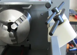
- added optional dirt caps for BracketX and BracketY.
Changes 01 Jan 2021:
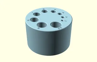
- added optional gauge holder "GaugeHolder.stl"
Tags
Model origin
The author marked this model as their own original creation. Imported from Thingiverse.


