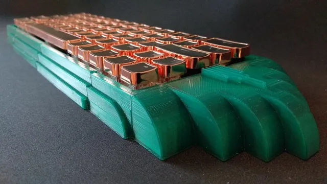
The Zaccone - A Kit for Converting Any Standard 60% Tray-Mount Into a Taco Bumper Gasket-Mount Keyboard
Description
PDFINTRODUCTION:
This is a kit for converting any standard 60% tray-mount keyboard (e.g., GH60 or DZ60) into a taco bumper gasket-mount keyboard. It consists of (1) the case and (2) gasket wings, which clip onto the plate. The gasket wings are rigid enough to keep the plate anchored to the case, but flexible enough to provide a softer and more delicate typing experience than other mounting methods.
My chief motivation for this kit (and my other gasket mount adaption kits) was to reduce the cost, and correspondingly increase the availability, of gasket-mounted boards. Although at the time of writing, commercial gasket mount kits made of plastic are becoming more widely available and are decreasing in price, a 3d-printed case still costs considerably less. An entire kit can be printed out for somewhere between 2 and 5 USD in filament. Further, excellent 3d printers can now be purchased for 200 USD or less. (Mine was 160 USD on sale.)
Another motivation for this kit was to avoid dependence on particular PCBs and plates. The GK61 Special, for instance, relies on the original iteration of the GK61, which possesses a special property that allows it to be converted to a ring gasket mount without any changes to the plate or PCB, namely, the plate extends beyond the PCB by about 1mm at the top and bottom. I am not even sure whether subsequent iterations of the GK61 will work. Similarly, the YC66 Special is based on the YC66 plate and PCB.
It has become increasingly difficult, however, to source original GK61s, and I am not sure how long the YC66/Womier K66/Gamakay 66 is for this world. This gasket mount adaption kit, by contrast, is not as tied to a specific substrate, so may have better longevity.
One final note about the design of this keyboard: it forces some tradeoffs that I did not anticipate when designing it. For example, if you want to reduce filament use and printing time, you will need to print the bottom half of the case upright, to avoid the use of supports in the tray cavity. But doing so results in pixelation along the incline, such that the top and bottom halves don't fit together completely flush. On the other hand, if you print the bottom half upside-down or on its side, the part that mates with the top half will be printed flat. This results in a more aesthetically-appealing case, but will require substantially more material and time to print out the support structures for the tray cavity. Additionally, instead of a simpler design, I incorporated curves, and, making matters, worse, decided to fillet the curves, which necessitates the use of further support structures. If I had proceeded with a plainer design, such complications might have been avoided.
TL;DR: I wanted to create a gasket mount keyboard case that (1) is cheap to produce; (2) is not dependent on specific plates/PCBs (such as my GK61 Special and YC66 Special kits); and (3) that still adequately produces the feel and sound of a gasket-mounted design.
INGREDIENTS
- M3 20mm screws x 4 (for upper portion of keyboard)
- M3 16mm screws x 4 (for bottom portion of keyboard)
- M3 nuts x 8
- adhesive poron, to be cut to size (I used the following 2mmT x 125mm x 1M poron: https://item.taobao.com/item.htm?spm=a1z09.2.0.0.67002e8dcgt1rA&id=596691601583&_u=820rh52kbe7d)
- a standard 60% tray-mount PCB and plate (e.g., GH60 or DZ60)
- internal weight (optional) https://item.taobao.com/item.htm?spm=a1z09.2.0.0.67002e8dcgt1rA&id=560138068179&_u=820rh52k68c4
- case foam (optional)
ASSEMBLY INSTRUCTIONS
(1) Print out the case. If your build size is sufficient (length >= 296 mm, width >= 132 mm, height >= 27 mm), then you will be able to print out the entire "CASE TOP HALF" and "CASE BOTTOM HALF" at once. For build sizes of <= 150 mm^3, I have subdivided the case into four parts: "case top left," "case top right," "case bottom left," and "case bottom right."
(2) Print out the gasket wings:
(a) "wing - upper left/upper right 2u" x 2
(b) "wing - upper center 3u" x 1
(c) "wing - bottom 2.5u" x 2
Note that the "wing - upper center 3u" is optional. (I have not tried omitting any of the corner wings.)
(3) Affix the adhesive poron (or some other gasket material) to the gasket wings, forming a "taco" bumper around the wing. (See Figure 1 in the photos above.) Lengthwise, the bumper should extend beyond the wing by about 0.5 mm on each side. This will prevent the sides of the wing from contacting the case.
(4) Insert switches and keycaps into plate and PCB.
(5) Clip the gasket wings onto the plate (not the PCB) at the positions indicated at Figure 2 in the photos above. (In Figure 2, and for the purposes of illustration only, I have shown only the wings, plate, and a few switches, to better demonstrate the placement of the wings. During actual assembly, however, insertion of the wings would generally only occur after all the switches have been inserted into the plate and PCB.)
(6) Once clipped into the plate, align the gasket wings with the corresponding gasket wells on the case; sandwich the wings between the top and bottom halves of the case; and screw the top and bottom halves together. The 20 mm screws are for the upper portion of the case, and the 16 mm screws are for the bottom portion of the case.
If you print out the case in four parts (i.e., "case top left," "case top right," "case bottom left", and "case bottom right"), you might, depending on the tolerances of your printer, consider gluing together only "case bottom left" and "case bottom right." That way, it will be easier to line up the screw holes on the top and bottom halves of the case.
The gasket wells are 4.5 mm high and the gasket wing height (without poron) is 1.5 mm. Thus, if you use poron of 2 mm thickness, the combination of the 1.5 mm gasket wing and 2 mm poron (folded over the wing, so the thickness is doubled) will result in a bumper of about 5.5 mm thickness. This means that the poron will compress about 0.5 mm total in the gasket wells.
TO DO:
- Hide nut holes. Try either capture nut method and/or heat threaded inserts.
- Hide case seams.
- Add magnetically hot-swappable side panels.
AREAS FOR FURTHER EXPLORATION:
- Vary gasket dimensions to determine effect on feel.
- Try different shapes for the gasket wing (e.g., trapezoid) and/or add support structures to the wing to provide rigidity (though the current instantiation is already pretty robust)--all within the constraints imposed by the space between plate and PCB and between switches.
- Try a gasket well spanning the whole length of the keyboard, as opposed to an individual well for each gasket wing, which would allow for choice in where and how many gasket wings you want to use.
- Try 1u gaskets, instead of, currently, two 2u gaskets (upper left and upper right), one 3u gasket (upper center), and two 2.5u gaskets (bottom).
- Try a long gasket well in concert with 1u gaskets, for further flexibility in gasket location choice.
Print Settings
Printer Brand:
XYZprinting
Printer:
da Vinci miniMaker
Rafts:
No
Supports:
Yes
Resolution:
300
Infill:
10
Filament: Unknown PLA
Red Copper
Category: ElectronicsTags
Model origin
The author marked this model as their own original creation. Imported from Thingiverse.