Wlan controlled lithophane cube

Description
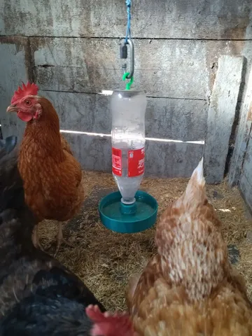
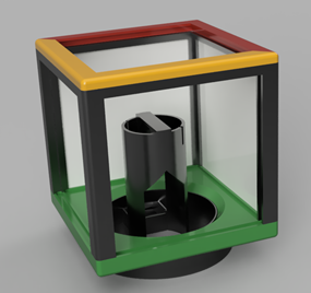
PDFWhether as a bedside lamp, desk lamp or as an eye-catcher on the sideboard, this cube can be used in many ways. The individual image selection (family, pets, ...) makes the project something very personal. Since the images are interchangeable and the top is rotatable, variety is provided. Via the wireless RGB light control, the "smart" idea is not neglected either.
The project
Suitable for: Electronics beginners and 3D printing experienced
Time required: approx. 6-8 working hours, approx. 86 hours of the 3D printer
Costs: approx. 30 €
You will need:
- 1x Wemos-D1-Mini
- 5x WS2812b LED strips (30LEDs/m)
- 1x diode (1N4001)
- 1x USB cable Micro
- 1x 5V power supply
- 3D printer with white PLA filament
The operating principle
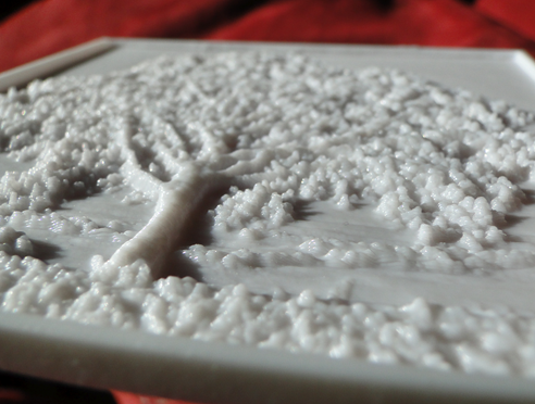
An existing image is converted for 3D printing in such a way that dark areas receive more material than light areas. This results in a surprisingly detailed grayscale image when backlit. The more precise(=time-consuming) the printing is, the greater this effect is.
From photo to 3D model
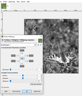
High-contrast photos are suitable as motifs, which can be adapted somewhat for the further steps using an image editing program (e.g. Gimp). For the cube used here, square images must be used. Use the selection tool "Rectangular selection" and the fixed aspect ratio 1:1 to select the appropriate image section.
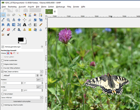
With "Crop to selection" only the selected section remains.
To work out the details better, the curve functions (Values, Curves) offer even more possibilities to optimize the image.
The easiest way to get a grayscale image is to drag the saturation slider to the left via Colors Hue/Saturation.
Now the image is saved as *.jpg on the hard disk (FileExport as...).
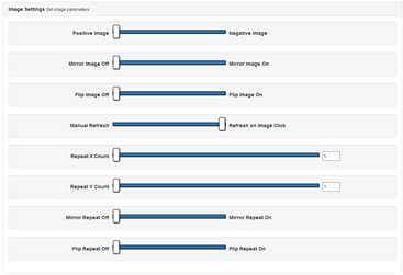
For the conversion of the 2D information to the 3D model the page https://3dp.rocks/lithophane/ is useful. After uploading the image under "Images", the appropriate parameters are used at Model Settings/Image Settings, as shown in the images.
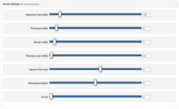
This results in a final format of 100x100x4mm which can be inserted exactly into the cube. The border of 2mm, gives the image a stability, but then disappears behind the frame.
If the browser crashes during the calculation, the "Vectors per Pixel" must be minimized to 5.
With "Download" you can download the *.stl file for the slicer. 5 different images are needed for the cube.
From 3D model to printout
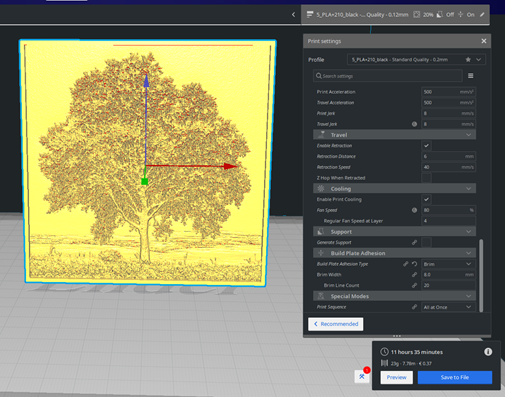
To convert the 3D model (*.stl format) into the machine code (*.gcode) a slicer program is needed. The free program Ultimaker Cura offers all features that are needed.
Since the setting of dozens of parameters must be adapted to the own printer / filament, I would like to go here only on the most important settings / tips and assume some basic knowledge.
The most important settings:
- Print image upright
- White PLA filament is best suited
- 0,4mm nozzle is sufficient
- choose layer height as low as possible (0,12 or 0,16mm)
- Infill to 100%
- Use brim for good adhesion to print bed
- Max 40mm/sec printing speed
Remaining 3D printed parts
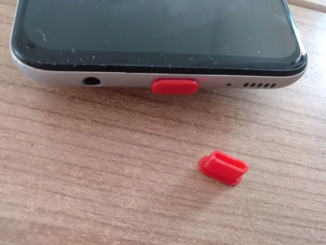
The remaining 3D parts can also be printed. A layer height of 0.2mm is sufficient here and reduces the printing time. For this purpose, I designed the parts in the CAD software Fusion360, which is free for home users, so that they can be printed without support. If all parts are available, they can be easily assembled. The models are also available in the download.
Wiring
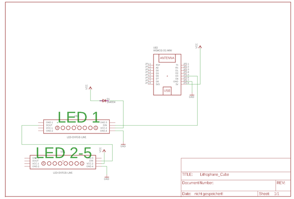
Since the WS2812b-LED strip works with 5V, but the output levels of the Wemos D1 work with 3.3V, a level adjustment with level shifters would have to be used here. In this case a simple diode in the supply line of the 1st LED is sufficient for the level adjustment. This ensures that a high level on the data line (DIN) is correctly detected. The remaining LEDs are supplied with 5V. This trick circuit was chosen because of the construction, since the first LED is mounted separately (on top) anyway. The remaining 4 LEDs can be glued as a band around the "lighthouse".
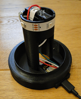
The diameter of the "lighthouse" is designed so that the horizontal LEDs are each offset by 90°. The Wemos-D1 can be snapped into the recess provided. The USB socket is then accessible for the connection cable.
Programming the microcontroller
The software used is the cloud-free and very versatile firmware Tasmota by Theo Arends. An already compiled version e.g. tasmota-DE.bin can be used.
Reflashing is possible with the software Tasmotizer via USB micro cable.
Be careful to really use a data cable here, which also has the necessary data line and is not just a pure charging cable!
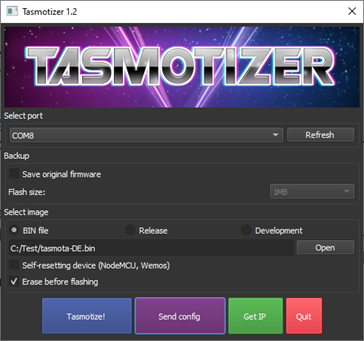
After selecting the correct COM port and the appropriate *.bin file, the controller is programmed. If the programming does not start, the reset button can be pressed briefly when plugging in to get into flash mode. Via the button "Send config" the WLAN data of the own network can already be transferred here.
After a restart, the controller registers itself in its own network. After the newly assigned IP address has been determined in the router, the device can now be further configured in the web browser (e.g. http://192.168.178.23).
The following settings must still be made:
Settings -> Configure device Device type to "Generic (0)". By saving, a reboot is executed.
In the same menu item we now select the setting "WS2812" for GPIO0 (D3). Save Restart.
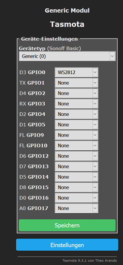
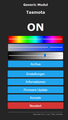
Already now the LEDs should be freely controllable via the sliders.
Settings / Other settings / Enter Device Name and Name.

If the "Emulation" option is activated on "Hue Bridge Multiple Device", the cube can be controlled by voice command via an Amazon Echo using the previously assigned name.
Setting a timer
In order to be able to switch on the cube with the sunset, for example, the location must first still be communicated. Via "Console" these parameters can be entered directly e.g.
Latitude 45.123456 (latitude of the location)
Longitude 8.123456 (longitude of the location)
TimeZone 99
->Timezone Europe with daylight saving time.
After a restart the values are taken over.
To switch on the cube with the sunset the switching operation can be set under Settings Schedule Settings like this:
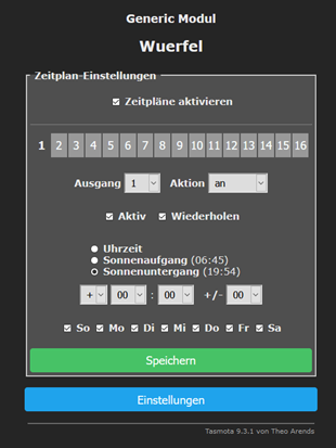
Switching off can be set to a fixed time via timer 2, for example.
Further possibilities
Since some other ports are still free, these can be used here e.g. for temperature or humidity sensors. Via the MQTT connection an integration into the Smart-Home is so easily possible.
Have fun with the replica
Tags
Model origin
The author marked this model as their own original creation.