Adjustment Jig for DeWalt Table Saw DWE7492
Description
PDFI found a well designed jig on the internet but because I already spent too much money on jigs and tools I built one myself. For your convenience I've included all Fusion 360 files so you can make changes to the design.
To make adjustments you need an indicator like this one. If you already have an indicator and you want use the jig as is, it is important that the mounting diameter of the indicator is 8 mm and the distance from the center of the spindle to the back is also 8 mm.
You need:
- all printed parts (4 nuts, 1 base, 1 T-bar and 1 indicator mount)
- 4 pc countersunk screws M5x20
- 4 pc M5 nuts to insert (height 4mm or less)
- a (digital) dial indicator
How to use on your table saw
Before you begin, disconnect the machine from the power source and read the owner's manual to locate the fasteners. To avoid kickback it is important that the rear of the fence is slightly wider (more or less 0.5mm or 0.02") than the front. The blade should be parallel to the mitre gauge slot.
Print instructions
In Prusaslicer (version 2.2 or newer), after slicing the 4 nuts, insert a pause (M601) at layer 13.20 mm (assuming you use 0.2mm layer height) right-clicking on the cross icon. The printer will pause before the selected layer is being printed. Insert the M5 nuts and resume printing when you are ready.
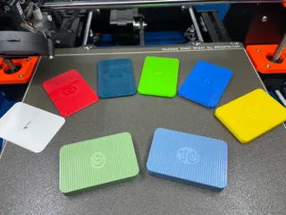
Place parts on the heated bed as shown on the photos.
Because it is a snug fit, it is important to have a properly calibrated printer. If the T-bar is too loose, you can tighten the screws slightly for a better fit.
Print settings and Filament
Layer height: 0.2 mm
Infill: 15%
No support, no brim, no raft
Filament: any
I printed the jig with Prusament Lipstick Red PETG on a textured sheet.
Model origin
The author marked this model as their own original creation.


