Railcore XRAT (X Rail Alignment Tool)
Description
PDFNOTE: This thing has been semi-superseded by the XRAT 2.0. The old design still works fine, but if you're working on a new build, I would suggest considering the 2.0. That said, it is a slightly harder print and does require additional hardware, so I'm leaving the original design available for those that would prefer it.
This is a screw-driven adjustment tool for the X linear rails of the Railcore II.
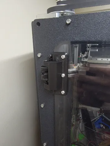
End caps are placed over the ends of each X rail and top caps are mounted to the top extrusion of the printer. This provides a known reference for rail height. With the rail loose on the extrusion, tightening the drive screw will raise a given end of the linear rail, while loosening it will lower it.
Because M3 screws have a known thread pitch of 0.5mm/turn, we can roughly estimate rail adjustment based on the number of turns:
| Turns | Travel | | --- | --- | | 1 | 0.5mm | | 1/2 | 0.25mm | | 1/4 | 0.125mm | | 1/8 | 0.0625mm |
Etc.
Note that because the rails extend beyond the ends of the printable coordinate space, these numbers will not match changes in bed deviation exactly. However, because we're working against fixed reference points, it's much easier to, e.g., raise the entire front rail a particular amount to help align it to the rear rail.
Also be aware that installing the tool on the left rear rail requires removing the X end stop switch and will require the rails to be centered on the extrusion due to space constraints. Home the printer before installing the tools and do not reboot the printer until finished.
(The endstop can be reinstalled with the tool left in place, but you will lose around 10-15mm of X travel by doing so.)
| Hardware required | Purpose | Quantity | | --- | --- | --- | | M3x10mm | Top cap to extrustion | 8 | | M3x3mmx4.3mm threaded insert | Drive screw into rail caps | 4 | | M3x20mm | Drive Screw | 4 |
Please note that the threaded inserts arenot the same as used in the Railcore BOM; the limited space available required smaller inserts to avoid warping the parts.
When installing, I'd recommend topping the rail out on the extrusion, then, with your thumb resting on the top of the rail, lowering them around 2 turns of the drive screw from the point you can feel the rail begin to move as a starting point. This will give you some adjustment range in each direction to start out.
An example post-adjustment macro is included. It performs a Z home, 3x bed leveling routines, Z home, and finally runs a bed mesh. Run once after initial adjustment, then make fine adjustments to the rail positions as necessary.
At this time, I have received reports that the part is compatible with the following motion system configurations:
- Standard/Gates idlers and pulleys with the 713maker idler mounts
- Magnum pulleys with the Mandala Roseworks Magnum idler mounts
- The 713maker Halo with standard/Gates pulleys
- The 713maker Halo with Magnum pulleys
If you happen to try another combination that isn't listed here, please let me know the results.
If you need any additional help getting things dialed in, I would highly recommend checking #help on the Railcore Discord.
Changelog
2019.04.25
- Changed thing name to XRAT to help reduce confusion with the kit rail alignment tool.
- Added confirmation of compatibility with Halo + Magnums.
2019.04.10
- Confirmed compatibility with Mandala Roseworks Magnum Pulleys and Idler Mounts. Adjustment of the drive screw will likely require a ball-end hex key due to tight clearance with the Magnum pulleys.
- Tentative confirmation of compatibility with the 713maker Halo
- Slight update to the usage instructions.
2019.03.17
- Initial publication
Print Settings
Printer:
Railcore II 300ZL
Rafts:
No
Supports:
No
Resolution:
0.2mm
Infill:
100%
Notes:
Print one pair of each component as-oriented.
4 perimeters. A short bridge is required for the rail end caps.
Post-Printing
All holes are intentionally modeled as very tight fits and are intended to be drilled out with a 3mm bit to ensure proper fit.
The threaded inserts will push waste material into the through hole of the top cap and will likely require cleanup with a drill and/or an M3 tap.
Category: 3D Printer PartsTags
Model origin
The author marked this model as their own original creation. Imported from Thingiverse.