Fusion 360 Thread Tests


Description
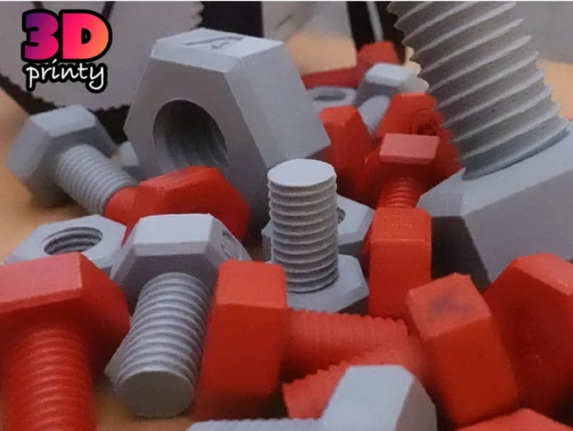
PDFThis is a print test for bolt threads created and modified in Fusion 360.
I needed a more consistent way to add threads to my projects - I used these test prints to play around with altering the standard threads generated in Fusion 360 to make them more 3D printer friendly.
Designations
All bolts shown are based on the ISO Metric specification for an M12 bolt with 1.75 pitch threads. The peaks and throughs for the threads have been blunted because most prints don't need extremely deep threads.
Bolt & Nut A
Tolerance: Default
Bolt & Nut B
Tolerance: Default + 0.05mm
Bolt & Nut C
Tolerance: Default + 0.1mm
Bolt & Nut D
Tolerance: Default + 0.15mm
Bolt & Nut E
Tolerance: Default + 0.2mm
How To Generate and Modify Threads in Fusion 360
Build the basic shapes for your bolt and nut (or hole).
The inner and outer surfaces that will be threaded should be touching. Do not attempt to create additional separation between the parts yet.
Apply Fusion 360's Thread tool to each surface. Set the "thread type" to "ISO Metric Profile" and use the coarsest thread count available..
Using the Press/Pull tool, blunt the peaks and troughs in the threads. I typically use 0.1-0.2mm, but this value will depend on the diameter of the bolt. This removes the thinnest part of the threads, which I find to be least reliable.
Use the Press/Pull tool agin to increase the space between the 4 surfaces that form the helix of both the bolt and nut. Example tolerances are listed above, but remember to divide those values in half, since you will be applying them to opposing faces from each part.
Tags
Model origin
The author marked this model as their own original creation.