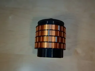
Harry Potter themed strongbox with 8-digit combination lock


Description
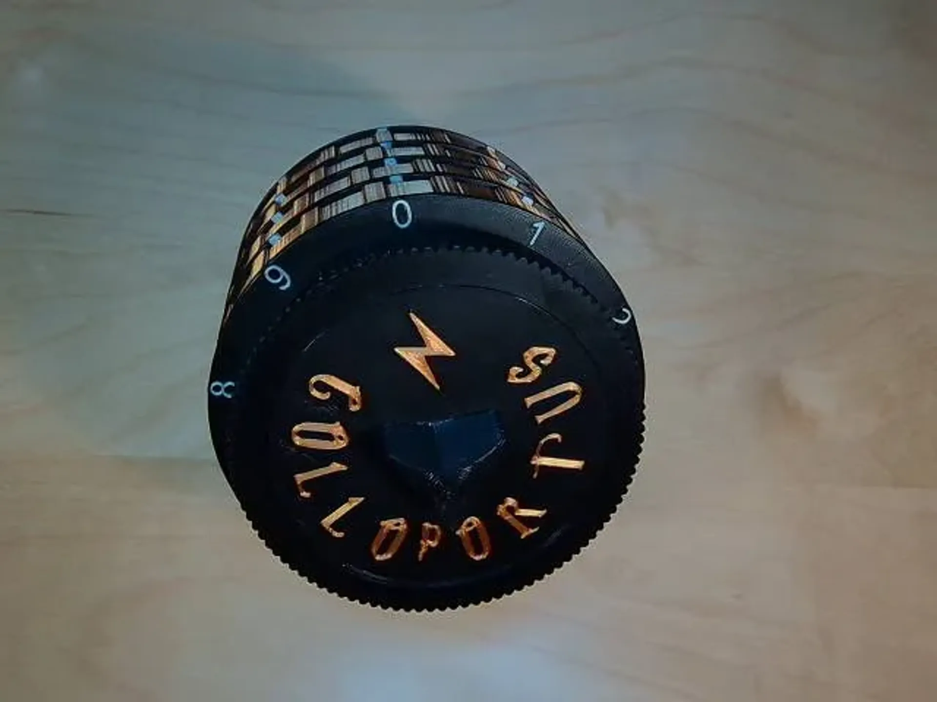
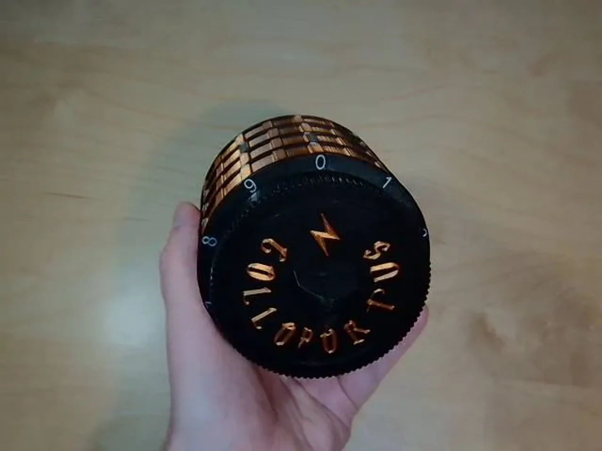
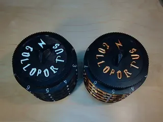
PDFThis is a Harry Potter themed strongbox with a programmable 8-digit combination lock.
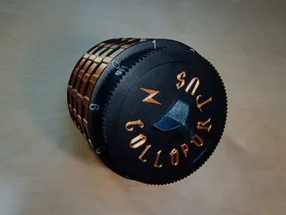
The lid is held firmly shut by the powerful locking charm Colloportus to ensure that only one properly schooled in the art of witchcraft and wizardry can access what dwells within.
If, however you have the secret in your command and also happens to be a true alumni of Hogwarts, then you can use your powers to invoke the unlocking charm Alohomora which will allow you access.
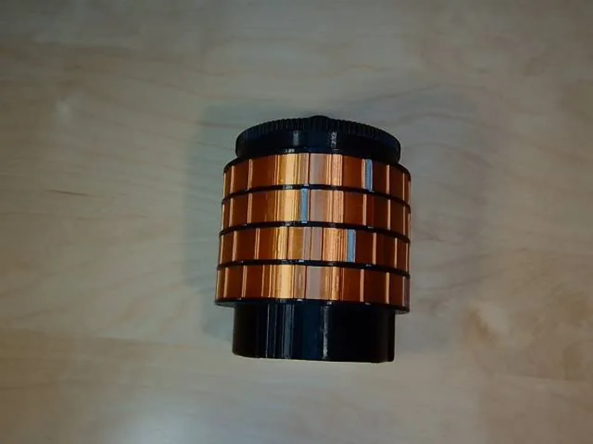
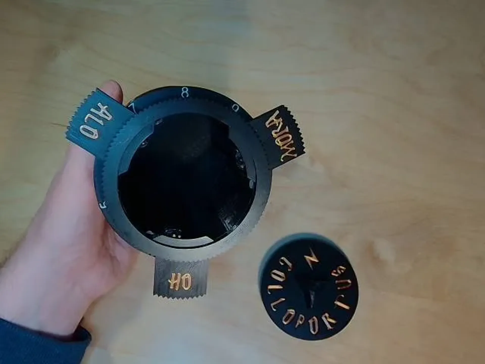
The combination to the lock consists of 8-digit, distributed over 4 separate 2-digit locks working in tandem. The combination is entered, as with any combination lock safe, by turning the dial first a full revolution left, then continue left to the first number. Then turn the dial right to the second number, and so on. The first pair of digits are entered on the first lock from the top, the second pair of digits on the second lock from the top, and so on.
Choosing the combination
The combination consists of 4 pairs of a “left-digit” and a “right-digit”. You need to select your code before printing as the “left-digits” determines what parts to print, see “What to print” below.
The combination is chosen freely and can be changed at any time by disassembling the box and change/rearrange the parts, but only as long as you have to current combination, see “Lost the code?” below.
Filelist
Allways use the gcode-files if possible, orientations, support structures etc. may be siginificant for proper function.
1: Strongbox - Main body parts_0.2mm_PLA_MK3S_10h14m.gcode
2: Strongbox - Lid assembly (Harry Potter)_0.2mm_PLA_MK3S_2h40m.gcode
3: Strongbox - Ring assembly top spacers_0.2mm_PLA_MK3S_5h10m.gcode
4: Strongbox - Ring assembly center spacers_0.2mm_PLA_MK3S_33m.gcode
5: Strongbox - Ring assembly bottom spacers_0.2mm_PLA_MK3S_5h5m.gcode
6: Strongbox - Ring assembly tics_0.2mm_PLA_MK3S_2h34m.gcode
7: Strongbox - Ring assembly numbers_0.2mm_PLA_MK3S_39m.gcode
8: Strongbox - Ring assembly turners_0.2mm_PLA_MK3S_6h8m.gcode
9A: Strongbox - Bottom (Harry Potter with English instructions)_0.2mm_PLA_MK3S_2h3m.gcode
9B: Strongbox - Bottom (Harry Potter with Swedish instructions)_0.2mm_PLA_MK3S_2h4m.gcode
10: Strongbox - Ring assembly lock ring (Right)_0.2mm_PLA_MK3S_1h50m.gcode
11: Strongbox - Ring assembly lock ring (Left 0)_0.2mm_PLA_MK3S_22m.gcode
11: Strongbox - Ring assembly lock ring (Left 1)_0.2mm_PLA_MK3S_22m.gcode
11: Strongbox - Ring assembly lock ring (Left 2)_0.2mm_PLA_MK3S_22m.gcode
11: Strongbox - Ring assembly lock ring (Left 3)_0.2mm_PLA_MK3S_22m.gcode
11: Strongbox - Ring assembly lock ring (Left 4)_0.2mm_PLA_MK3S_22m.gcode
11: Strongbox - Ring assembly lock ring (Left 5)_0.2mm_PLA_MK3S_22m.gcode
11: Strongbox - Ring assembly lock ring (Left 6)_0.2mm_PLA_MK3S_22m.gcode
11: Strongbox - Ring assembly lock ring (Left 7)_0.2mm_PLA_MK3S_22m.gcode
11: Strongbox - Ring assembly lock ring (Left 8)_0.2mm_PLA_MK3S_22m.gcode
11: Strongbox - Ring assembly lock ring (Left 9)_0.2mm_PLA_MK3S_22m.gcode
What to print
Print all the files 1 through 8, and then either file 9A or 9B.
Print file 10, and 4 of the files named 11 depending on what “left-digits” you have selected.
Files 2,6,7,8 and 9 are dual-color prints that will require two different colors of PLA.
Lost the code?
So far, I don’t know that anyone has been able to pick the locks without breaking it. If you have done so I would love to hear from you.
The best option you have if you lost the code is to break the three tabs protruding slightly from the bottom cover, and print new ones. Use a small knife (or a Dremel or similar) to carve away the bottom part of the tabs. The bottom parts are thicker than the holes in the bottom cover, so if you grind away the bottom part of the tabs they could pass through the hole and you should be able to remove the bottom cover.
Build instructions
Some parts have quite narrow tolerances and needs to be fitted together with some precision, so depending on the precision of your print and materials used etc. there may probably be some work needed here and there to make sure everything fits together as expected. Always make sure the parts fits nicely before applying glue or making final assembly.
Make sure you have all the necessary tools ready before opening the super glue.
1. Clean up the parts
Start by cleaning up the main body from support structures on the inside. 25mm up from the bottom there are three notches that later will be used to hold the bottom cover in place. Clear away the supports and make sure the notches are free from debris. Insert a flat file with a slight downwards angle in the vertical slit at each notch and give it just a few strokes (see video) to make sure the notch is clean and has no sharp edges from the support structures.
The turner rings of the lock assemblies has a noths on the inside that is printed with a support structure from the build plate. It is important that the notches are not wider than the rasied “track” on the inside of the rings, and for this purpose it is actually 1 layer narrower than the track. Make sure that the remains of the support structure is completely removed so the notch does not sit proud of over the track.

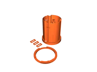
2. Glue the body together
The body consist of the main body part and a ring that is superglued to the top. Use a sandpaper to take the shine of the top of the main body and from the bottom of the ring to allow the glue better grip. Apply superglue to the ring and the guide pins, but avoid getting too close to the outer edge and the openings so that excess glue doesn’t come out where can cause problems. If glue comes out on the inside, just sand it down after it has hardened fully.
Press the parts firmly together and make sure there are no gaps. Leave to harden fully with some weights on top of it.
3. Glue the lid together
The lid consists of a top cover, a cogwheel, a knob and an M3 bolt. The top cover has a square hole that fits the axel of the cogwheel, and the knob has a square hole in the bottom to fit on top of the cover. Make sure you get the orientation of the knob correct so that it fits the decorations on the cove the way you like it. Do not use to much glue as it is very easy to get glue coming out under the knob when the parts are pressed together. Finally secure everything with the M3 screwed into the knob from the bottom of the cogwheel.
4. Glue the turner rings
The turner rings have a marker on them to indicate the number for the combination code. To avoid a long print with continuous color changes these markers are instead printed as separate parts and superglued in place.
The markers are slightly conical, and should fit nicely in the space in the turner ring with the narrow side down. Make sure you have some means to press the parts firmly together until the glue sets.
5. Fitting of the rotors and dead bolts
The rotor consists of o long semi-circular rod with a cogwheel at the end which will interlock with the cogwheel in the lid-assembly. The rotor also has to two “slave rotors” which are similar but are only the top part of the rotor. The dead bolts are three flat parts that slides in and out of the lock when the rotor and slave rotors turn. The smooth movement of these parts is essential to the function of the lock.
First feel the rotors with your hand and sand of any roughness. Then take dead bolts and fit their slots in the body to make sure that they fit snuggly but do not stick on anything, such as excess glue from the body and body ring assembly.
Due the orientation in which the body was printed, one of the three vertical slots in the body will let the rotor turn freely while the other two will probably have some snags. Try all three and mark the slot that fits best. Some sanding may be required, the rotor must be able to turn easily in the slot.
6. Mount the rotors and dead bolts to the body
The dead bolts need to be inserted in the correct order as their decorations indicate. The 0 on the combination dial is where with the rotor is, so it is natural to regard this a “up”. Therefore, the dead bolts should preferably be ordered counterclockwise with the first dead bolt in the second slot from the rotor. Install the dead bolts and make sure they move smoothly.
Push all dead bolts in to their locked positions, and insert the rotor in the selected slot. Use some tape to keep it in place.
Insert the slave rotors in the other slots and make sure all rotors are all the way in so the interlock with the rack in the underside of the dead bolts. Put the combination dial on the body locking the slave rotors in place. Look to make sure the deadbolts are where you want them.
Temporarily remove the tape, making sure the rotor does not fall out or the combination dial is displaced, push all deadbolts out to the open position. Place the lid in the opening and test the lock mechanism by turning the knob. Make sure all parts move freely and do not require too much force.
7. The lock assembly
At this point you should already have decided the combination and printed the “left-digit” lock rings needed. There are four lock assemblies and each requires:
- One top spacer and one bottom spacer (identical but printed with different sides against the print bed to create the smooth surface on different sides)
- One center spacer, a thin spacer keeping the lock rings from moving together
- One left lock ring representing with the digit of your choice
- One right lock ring
- One turner ring to operate the lock
- One “combination notch” ring with marks for the number on the combination dial
Start by carefully turning the box upside down, open the lid and remove it.
First put a top spacer on, with the smooth side up.
Now consult your note with your code and pick out the first needed left digit lock ring. The number of the lock ring is indicated by the number next to the little notch on the lock ring. In my case I have selected (left) 4. Place the lock ring with the number side up.
Put on a center spacer and then a right lock ring, numbers up.
Take a turner ring and place it over the entire set of rings making sure that the notch on the inside slides into the gap in the right lock ring representing the second digit of your combination, in my case (right) 7.
Place a bottom spacer with the smooth side down and top it off with a “combination notch” ring.
Hold everything carefully in place and turn the box around so that you can check all the dead bolts work in tandem when you close and open the lid. When the dead bolts are in lock position the flat side of the main rotor should line up with side of the body.
Repeat three more times to complete all 4 lock assemblies.
8. Doublecheck the combination
When all four lock assemblies are in place it is time to doublecheck the combination so nothing has moved out of place during the process.
Put the bottom cover, hold everything together, and turn the box over. While letting the box stand firmly on the table to keep all the parts in place, put the lid in, close it and scramble the combination by randomly turning the turner rings.
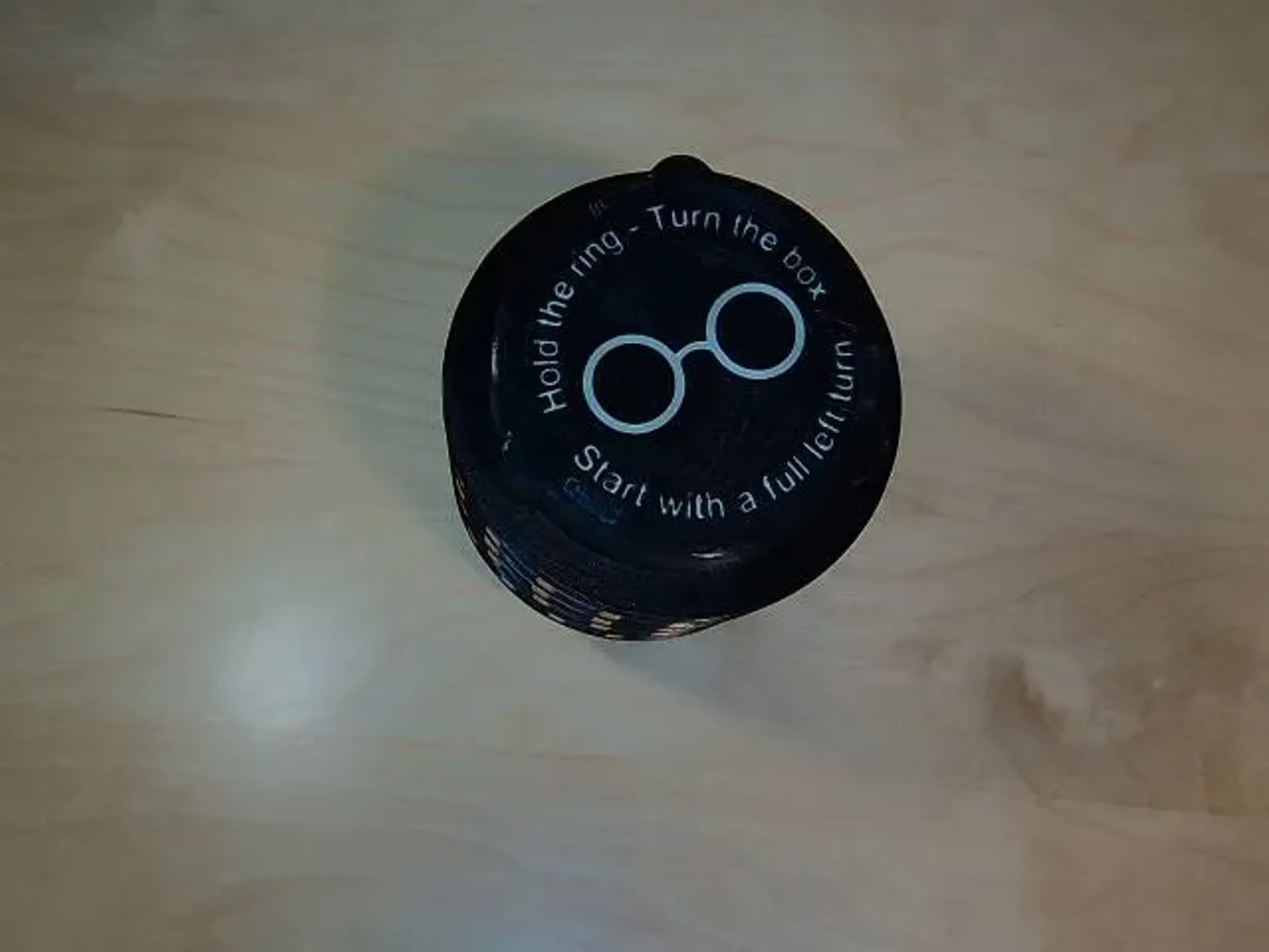
Test your combination! Remember “Start with a full left turn” which basically means that you should pass your left digit once before setting it.
If you can’t open the lock, you have to disassemble the locks one by one and find the offending right digit setting (the left digits are “hardcoded” so they cant be wrong if you assembled it correctly)
9. Seal the bottom
When you are satisfied with everything it is time to seal the box closed. After completing this section, you cannot get in unless you have the correct code (see “Lost the code?” below).
The box is now complete with all lock assemblies and the bottom cover in place. The only thing remaining is to fasten the bottom cover to the main body. This is made by the three tabs printed with the main body parts.
Remove the bottom cover and insert the tabs into the slits. Sand the tabs slightly if they don’t fit correctly. Inserted into the cover they are supposed to sit proud by a millimeter or two.
Carefully replace the cover with the tabs inserted onto the bottom of the box, making sure the tabs slide on to the notches inside the main body (it is now the cleaning in step “1. Cleanup the body“ pays off). Press the tabs firmly and hopefully you will feel the tab click onto the notch.
Turn everything over and use a screwdriver to ensure the tabs are firmly seated onto the notches.
Replace the lid with the part you want “up” at the 9-position, which will put it at dead center when locked.
Done!
Tags
Model origin
The author marked this model as their own original creation.


