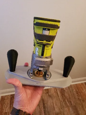
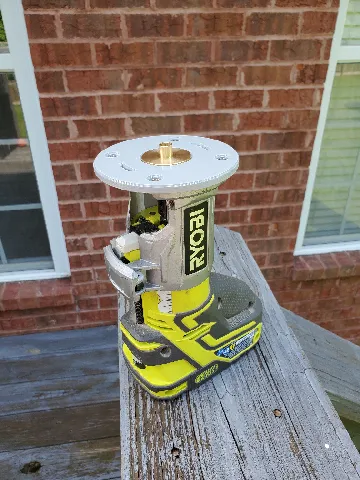
Ryobi 18v Router Base Plate with Edge Guide

Description
PDFThis router base plate was inspired by the Rockler universal base plate.
https://www.rockler.com/universal-router-base
Currently this one is only designed for use with the Ryobi 18v trim router because that is the only hole pattern I have.
This base plate additionally works with these template bushings from harbor freight
https://www.harborfreight.com/router-template-guide-set-9-piece-59369.html
Print settings:
Material: PLA, ABS, anything stiff really. PETG might flex a bit too much
Infill: For the base plate I would recommend something like grid, cubic, or honeycomb at 30% or greater. For the other parts its less important so I don't have a recommendation
Walls/Perimeters: For stiffness I would recommend at least 4 walls/perimeters for the base plate. And again the other parts its less important so 2 or 3 is probably sufficient for them.
Supports: If oriented correctly you should not need any supports on any of the parts. I believe the coordinate systems on the parts should pull them into the slicer in the correct orientation automatically. The bolt knobs and handles may need a brim to increase adhesion due to the small surface areas contacting the bed.
Size: All parts will fit on a 210mm x 210mm build plate. Not all at the same time though and the base plate will have to be rotated.
To assemble you will need :
5x) ¼-20 hex nuts
3x) ¼-20 x 1 ¼ (or longer) hex bolts, alternatively you could use 2 hex bolts and a pan head bolt. The bolt that holds the handle on will not protrude from the bottom face of the base plate either way.
Assembly instructions:
- Drop a nut inside the handle and place the handle in the handle recess on the base plate being sure to align the slot in the handle with the corresponding protrusions in the base plate.
- Install a bolt up from the bottom of the base plate (hex head or pan head) into the handle and tighten the bolt. I found it helpful to push down on the nut from above with a screw driver until I was able to get the bolt to begin threading in.
- Install the remaining 4 nuts into the edge guide on the side with the hex shaped recesses. These are designed to be a tight fit, you may need to tap them in with a mallet.
- Next install the remaining hex head bolts into the bolt knobs, these are also intended to be a tight fit and may need to be tapped in.
- Lastly, if the edge guide is desired, place it on the bottom side of the base plate with the nuts facing away from the base plate and simply line up the thru holes on the edge guide with the slots on the base plate and thread the bolts with the knobs in from the top side of the base plate.
The slots and edge guide are designed for the maximum range of motion, if one set of holes wont allow for you to position the edge guide where its desired, the second set of holes may be able to get you there. Positioning the Edge guide may be tricky so I recommend measuring several times prior to making any cuts. Additionally there are two ways to use the edge guide, you have the flat side which is ideal for use with straight profiles, and you have the rounded side which is ideal for round profiles. I would encourage checking out the video on Rockler's website (linked above) to see the intended use of each side.
Tags
Model origin
The author marked this model as their own original creation.