K1C (K1 K1 Max) Chain delete Supportless version available

Description
PDFFast Print Guide to Remove the Chain on K1 Model Printers
Tools and Materials Needed:
- Allen wrench set (included with your printer or aftermarket versions)
- 3–5 small zip ties (I recommend neon-colored ones for visibility)
- Filament: PETG, ASA, ABS (PLA or PLA+ may work, but I recommend printing printer components in ASA-CF)
- A braided wire sleeve (similar to the ones found on older Ender 3 printers)
Search for "wire braided sleeve" on Amazon to find suitable options.
Instructions:
Turn off your printer! Ensure the printer is powered off completely before proceeding.
Detach the chain from the toolhead:
- Use the large Allen key from your tool set to remove the chain attachment from the toolhead.
- Carefully remove the chain from the wiring and Bowden tube, taking care not to damage any components.
Remove the toolhead cover/fan assembly:
- Access the main wire connected to the toolhead PCB.
- Note: Your setup may look different from mine, as I use a custom cooling system. If you’re curious, here’s my setup: The Skeletor Cooling System for Creality K1 Series.
Unplug the main wire:
- Gently unplug the white connector from the toolhead PCB.
- Be extra cautious not to damage the socket during removal!
Thread the plug through the printed part:
- Pass the wire through the braided wire sleeve.
- Pass the plug through the larger hole in your printed part from the top.
Reconnect the main wire and reassemble the toolhead:
- Reconnect the main wire to the toolhead PCB.
- Reattach the toolhead cover/fan assembly securely.
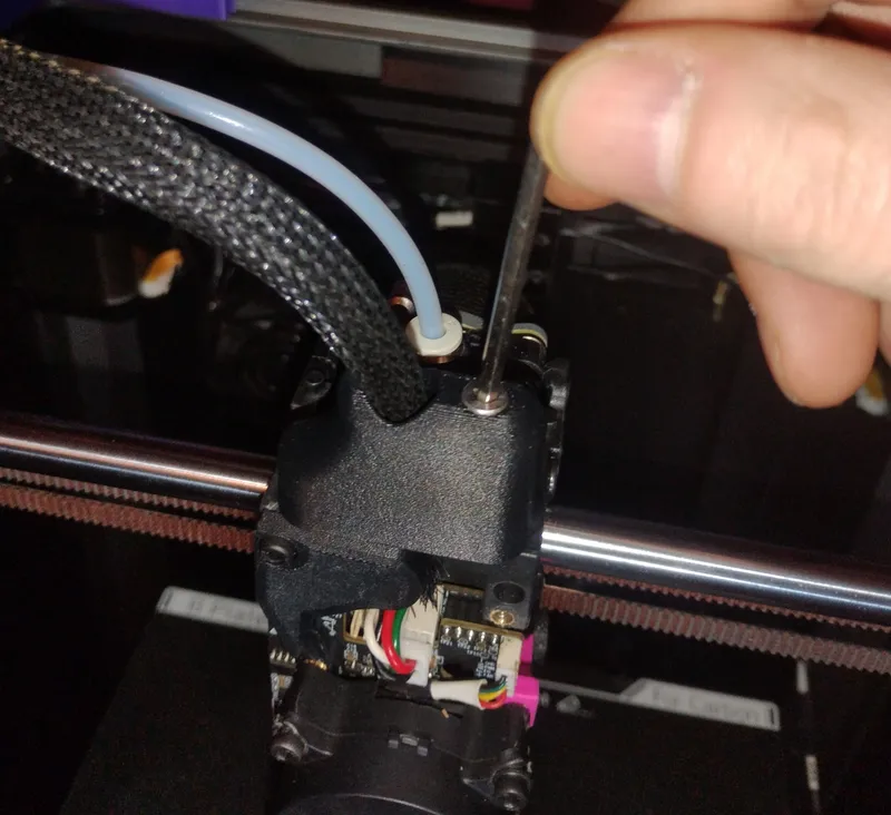
Align the printed part:
- Position the peg holes on either side of the printed part.
- Insert the screw (previously holding the chain) into the appropriate hole and tighten it. Your setup should now resemble the example image provided.
Zip tie the Bowden tube and wire sleeve:
- Use zip ties to secure the Bowden tube to the braided wire sleeve.
- Additionally, zip tie both the sleeve and Bowden tube to the rear chain bracket.
- Use the existing screw holes from the chain fixture for optimal positioning.
Run a self-check or input shaper:
- If your printer is rooted, run an Input Shaper calibration.
Disclaimer:
I have done my best to ensure this guide is clear and beginner-friendly. However, any damage resulting from following (or mis-following) these instructions is your responsibility. If you find any errors or need clarification, please let me know.
I assume no liability for any issues resulting from this guide.
Happy Printing! 🎉
Tags
Model origin
The author marked this model as their own original creation.


