3D Printer Emission Sensor Array (Sensorbox v2)
Description
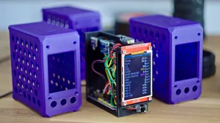
PDFThe original Sensorbox received quite of interest from people wanting to build one for themselves, but it was never designed for that - this one is! Using cheaper components, a more modern microcontroller and a streamlined design for the printable parts, I felt this Sensorbox v2 is something I can actually put out there and recommend you to build as well.
This is a project that hinges on Home Assistant and runs their ESPHome framework, making it easy to visualize the collected data and automate actions based on what you're seeing, e.g. turning on ventilation or air filters. However, it also means that you should have a Home Assistant running on a Pi or in a VM to properly use the Sensorbox - but trying Home Assistant is something I'd recommend to anyone whether or not you're also building a Sensorbox! Nonetheless, there is also a ready-to-flash firmware available that configures the Sensorbox for standalone use without Home Assistant (more info below).
This v2 version also uses a couple of newer sensors that are more easily available. You can mix and match sensors based on your needs, and with the ones that are supported, you should be able to cover most scenarios. It's also now based on a core PCB, which only costs around $5 to get 5 pieces made and shipped. This enabled me to build it around the $2 ESP32-S2 Mini instead of the buggy $6 ESP32-WROVER, adds flexibility for using different sensor loadouts and screens and probably saves you another $2 in jumper cables. So, essentially, the PCB is free ;-)
I like cheap things, so all of the components are readily and cheaply available from sources like Aliexpress. But because sellers frequently change their prices, the affiliate links below only point to searches. Pick the cheapest one that look like the ones I used and comes with free “Choice” shipping. Some of the parts are also available cheaper in their separate “bundle deals” section.
Sensor Selection
There are five recommended core sensors that cover most of the bases, plus a selection of supported sensors as alternatives - these are all enabled in the sample config files and simply need to be plugged in to start providing data. But because ESPHome supports a massive amount of other technically compatible sensors that could all be useful, the main PCB has all of the spare microcontroller pins broken out, and you can connect whatever you want as long as you add the matching config options.
Temperature / Humidity
Recommended
- AHT20 + BMP280 (cheap, ubiquitous, good consistency)
Supported
Compatible
- Any other I2C-based temperature / humidity sensor
- DS18B20-based sensors
CO2
Recommended
- SCD40 (compact, modern, accurate)
Compatible
- MH-Z19 (as long as you don't also use up both serial ports by plugging a ZE08 and PMS5003 at the same time)
Particles
Recommended
- PMS5003 (fairly ubiquitous, accurate enough)
Compatible
- PMS5003S (hard to find, integrated formaldehyde sensor)
- PMS7003 (compact, but requires additional adapter PCB)
- SDS011 (takes up the entire serial carrier, but may offer better calibration)
VOC / Gas
Recommended
- SGP30 (reports ppm, as well as an estimated CO2 value.
Important - the SGP30 is a 1.8V part while the PCB supplies 3.3V, so make sure to get a version that comes with an onboard regulator, as seen in the video around 5:39. These typically come with angled pins that can be bent straight and shortened.
The smaller GY-SGP modules has the necessary regulator on the back side and can plug into the SGP4x header. - ZE08-CH2O (formaldehyde-specific sensor)
Important The previous Sensorboard PCB r1 erroneously provided 3.3V to the ZE08's supply voltage pin labeled “5V”. The ZE08 is not rated to run at 3.3V (it might still work fine), but you can simply work around this by supplying it from one of the 5V pins on the spare GPIO block (the column labeled “5”). This is fixed in the current r1.1 PCB.
Supported
- ENS160 + AHT20 (cheap, but fairly unreliable absolute VOC ppb reporting due to auto-calibration, also reports eCO2)
- SGP41 (modern sensor, but ESPHome does not support the proprietary algorithm to convert the VOC index to actual ppm, so it will only report a relative index from 1 to 500.)
Compatible
- CCS811 (classic sensor, pin compatible to the ENS160 + AHT20 boards)
- BME688 from Adafruit (fairly expensive, requires proprietary BSEC2 algorithm to be useful, supported by ESPHome)
- MQ-7 CO (sensitive to carbon monoxide, requires modification, usually not needed for 3D printing, can be configured to use e.g. to the pins in the ZE-08 or PMS header)
Incompatible / Not recommended
- AGS10 (cheap, good readings, but requires 15kHz I2C frequency which the ESP32-S2 does not support with ESPHome)
- BME680 (expensive-for-what-it-is, end-of-life sensor with frequently erratic readings)
Recommended combinations
Here's how I'd kit out the Sensorbox for monitoring different scenarios:
Filament printing
AHT20 + BMP280, PMS5003, SGP30
Resin printing
AHT20 + BMP280, SGP30, ZE08-CH2O
Home air quality monitoring
AHT20 + BMP280, SCD40, SGP30, PMS5003 (optional), MQ-7 if you have a room-air-dependent furnace or fireplace
These should give you a good sense of what levels of air contamination you're dealing with - in this case, less contamination is always better.
Other required parts
Printed parts
Parts can be printed in any material, any color, no support material required.
For the latest Sensorboard PCB r1.1, print:
- Shell r3
- Serial Carrier r3
- LCD Spacer Left & Right r2
For the previous Sensorboard PCB r1, print:
- Shell r3
- Serial Carrier r2.1
- LCD Spacer Left & Right r2
Main PCB
Use the .zip file to order. I've added the r1.1 version to address some of the issues that became apparent when the r1 version was assembled out in the wild. The versions are pin-compatible, so they run the same firmware. They will fit inside the same printed shell, but the r1.1 version uses a different printed Serial Carrier.
Electronics / Mechanical
- ESP32-S2 Mini: Check that it explicitly has PSRAM ("N4R2" variant), required for running a screen
I'd recommend cutting one of the pin headers short and leave the ESP's “3V3” pin unpopulated. - MP1584 3.3V regulator (try to get the “fixed 3.3V” version, if you get the “adjustable” version with the potentiometer, you'll need to adjust it before assembly)
- 2.8" SPI TN screen, no touchscreen layer, ILI9341 (though other pin-compatible types may work with minimal config changes)
- 4.3mm x 6mm x 6mm tactile button (4pin, optional, but then the nice button panel up top won't do anything)
- Standard male / female pin headers
- “Dupont” style female crimp connector for the PMS5003 and ZE08 (alternatively, solder the wires straight to the PCB)
- 4pcs M3x25 cap-head screw (or similar)
- 4pcs M3x10 countersunk screw (or similar, the countersunk is just for aesthetics)
- USB-cable for power
- 1 small zip-tie
The PCB also allows for plugging in a crisp 1.3" IPS screen, a 2.13" e-ink panel or running with no screen at all. The alternative screens require config changes, but omitting the screen should work with no changes. If there's interest, I can redesign the case to support these alternative options!
Assembly / Setup
That's what the video is for, so… watch that please? The mechanical side of things is pretty straightforward, but configuring the ESP is a process that requires some hoop-jumping if you've never done it before, so I've tried to cover all the details there.
Official guide for setting up Home Assistant OS and ESPHome (as an add-on inside Home Assistant)
If you've got any problems or suggestions, please leave a comment here or under the video!
Firmware versions
If you're using the Sensorbox with Home Assistant, the STANDARD config file can be used within the ESPHome compiler.
The STANDALONE version has WiFi disabled by default and will not connect to Home Assistant. For that to work, it has ESPHome's failsafe mechanism disabled that would reboot the ESP after a while if it wasn't connected to a Home Assistant setup.
It can still be reflashed with a new version (STANDALONE or STANDARD) at any time by plugging the sensorbox into a computer and using the ESPHome web flasher again. Alternatively, a new firmware can also be flashed wirelessly through the AP mode, which can be enabled or disabled by holding the top button for three seconds.
Updates
2024-11-20
- ESPHome config added (includes new adaptive screen layout)
2024-11-30
- Updated description with errata note for ZE08 pinout
- Uploaded r3 and r1 versions of the shell .stl, providing more options for the screen bezel region
- Updated ESPHome config, as the current ESPHome compiler added stricter checks that failed with the original config
2024-12-01
- Created and added standalone firmware versions for use without Home Assistant
2024-12-10
- Added new bugfix Sensorboard PCB r1.1:
- ESPHome config remains identical to r1 PCB
- Improved thermal decoupling of AHT20 and SHT40 sensors - new position, double-walled thermal shield, removed ground plane around sensors, added PCB slot
- Fixed 5V pin for ZE08
- Deleted MQ7 header due to an unsuitable pin choice. Switching pins around would have broken software compatibility with r1. MQ7 will make an appearance again with the upcoming r2 PCBs.
- Separated 3V3 supply between ESP32-S2 and rest of board, added additional capacitor footprint for ESP32 3V3
- The r1.1 PCB is currently untested (I have put in an order for new PCBs), but as it only contains minor bugfixes and is otherwise electrically identical, I don't expect any regressions to pop up.
- Added Serial Carrier r3 to account for new ESP32-S2 position and changed temperature sensor locations
- Thanks everyone for finding issues and providing great suggestions!
2024-12-11
- Added serial carrier r2.1 (for Sensorboard r1) with thinner heat barrier and cutout to avoid pressing the ESP's boot button when assembled
UPCOMING
- New PCB revision:
- Plug-in options for ESP32-C3 and ESP32-S3, as the S2-Mini boards seem to fluctuate greatly in reliability
- Optional plug-and-play JST 1.25 connectors for ZE08 and PMS5003
- Optional Qwiic connector for easier sensor expansion
Model origin
The author marked this model as their own original creation.


