Piphex

Description
PDFSummary
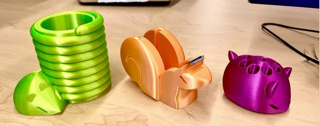
This little doobie is called “Piphex,” (pronounced PAI-feks,) short for “Print-in-Place Hexagon.” Aside from the very cool, very stupid name, it’s a half-demonstration-of/half-experiment-with print-in-place (PiP) 3D printed components. The idea behind a PiP is that it can be printed in one go, but with multiple moving parts permanently retained inside each other in a way only possible with 3D printing. Thus, it is a complex object with moving parts that is “printed in place” already assembled.
Assignment
The assignment given was: “Using sketch offsets and drafted extrusions/cuts, you will create a telescoping fidget device.”
In Piphex’s example, I wanted to push the boundaries of this repeatedly nested telescoping PiP… stim toy? …fidget? …thing, by subdividing the nested sections of the initial hexagon into lesser polygons. I put triangles in it!
Constraints
- The sketch must begin with a constraint box, (center-rectangle created from the origin)
- Your outermost outline must fit within an 8cm x 8cm box or equivalent area (64cm2)
- Dimensions/Relations should be efficient.
- It is not required to fully define your entire sketch, but it will help.
- The sketch must contain zero error messages.
- Demonstrate efficient use of “Offset Entities”
Design Process
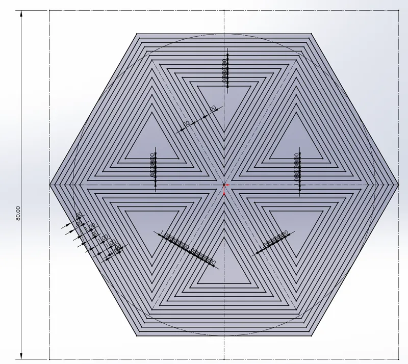
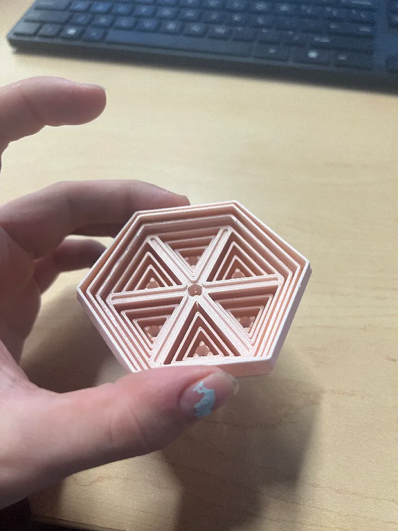
It started with this sketch, with a series of inward 1mm offsets. After 6, the hexagon is hex-cected into 6 triangles using construction geometry, which are then offset inward 6 more times. Pretty cool!
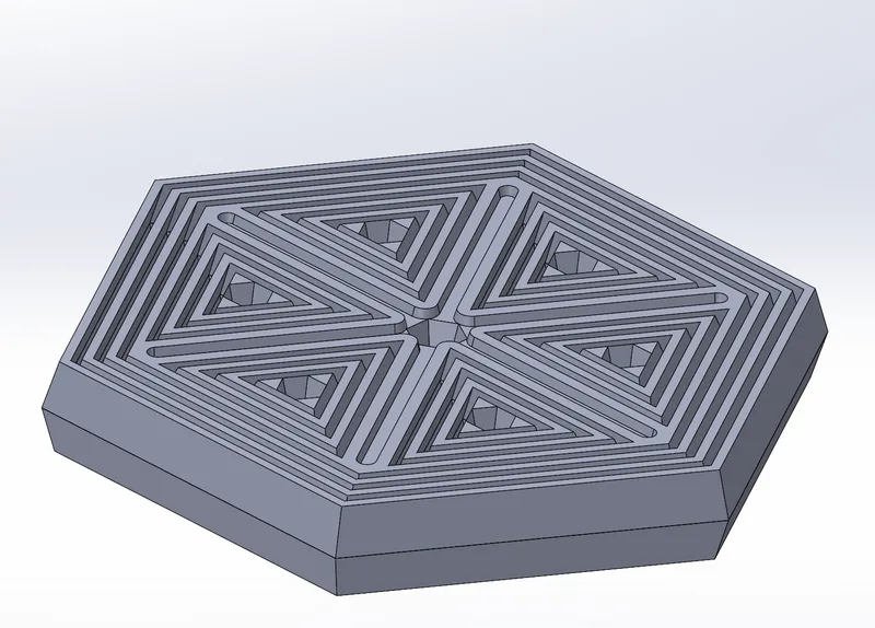
After repeatedly extruding and cutting inward with a draft of 15 degrees, this creates nested segments that are trapped inside each other when printed.
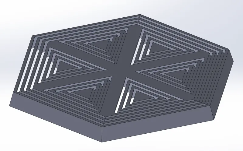
…or they will be, once the bodies are mirrored. Fun details too, cuz why not?
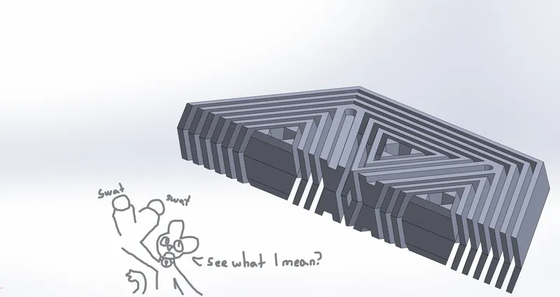
A bisection shows how each segment is trapped inside the previous, but still has wiggle room to move around.
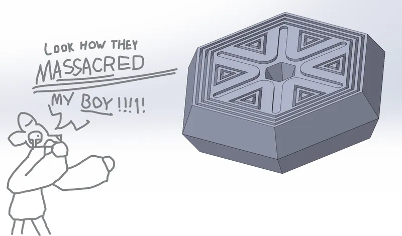
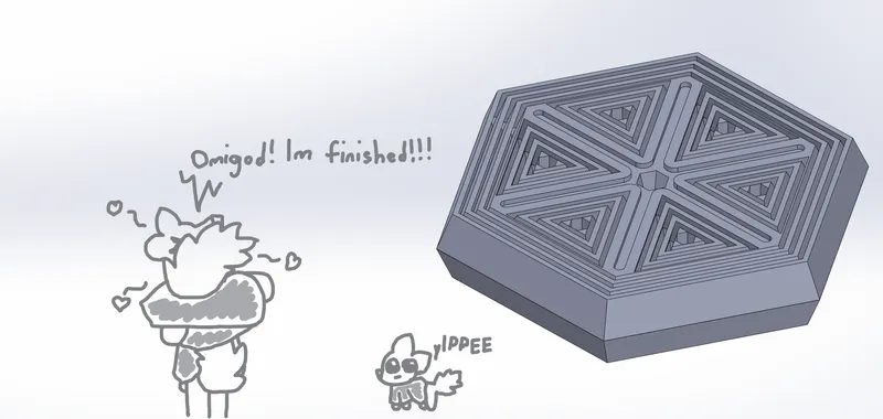
It’s finished, and print!
However when this draft was printed there was a…

…problem.
So, why did this happen, and how do you fix it?
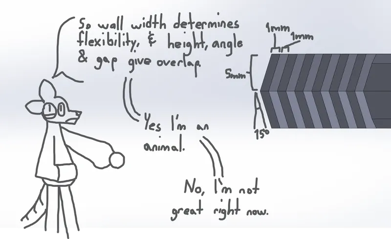
Well, this part and Print-in-Place parts generally have a few defining dimensions, which are:
- the shape of your whatever
- the thickness of the segment walls
- the height of the walls
- the width of the gaps between the walls
- the angle of the extrude and cut drafts, basically each wall’s “lean”
What these should be depends on that first one, whatever shape you’re making a PIP out of. Basically, it’s all about the overlap between each segment, the “retaining lip” of the nested parts. A balancing act between freedom of movement and not letting the parts fall apart all over the floor. The angle and height and the gap determine how far each segment will reach over the next part, and the thickness of the wall will control how flexible or rigid the parts are. The more flexible, the easier it is for interior segments to compress and squeeze past the retaining lip.
In Piphex 1.0’s case, the retaining lip just barely overlaps the next segment. The problem is that flexibility, and the shape. See, the triangular inner segments are retained just fine at the same dimensions, for two reasons. First, they’re smaller, and surrounded by a thicker frame segment; that stops them from flexing. But also, they don’t have opposing corners. This limits the amount of travel they can get, as the geometry of corners nesting would allow them to go further than just 1 mm relative to the opposite side, allowing just enough space for the opposite corner to squeeze in just a little and pop out.
The first solution was to just make the whole thing taller and the angle steeper. Behold, Piphex 2.0: double the height at 1 cm per half instead of 5mm, with an angle of 25 degrees. This… was severe overkill.
Not only was it unnecessary for the center, because - as mentioned, the triangles were already being retained fine - but it obliterated all the pretty details! The six-line star got its proportions all messed up, and the triangle details are just gone!
After some iterations experimenting with height and slope, I settled on this: Piphex 1.2. It had a subtler extrusion of 7 mm, and the slope was a shallower 20 degrees on the problem hexagons, while remaining the original 15 degrees in the center triangles. This led to a wall that got skinnier (weaker) on the outside edges of the hexagon that contained them, but the thicker inside walls of that hexagon made up for it.
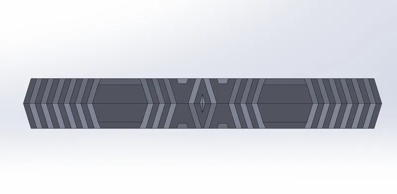
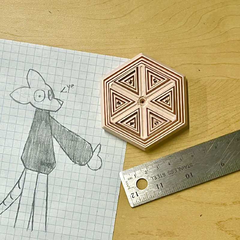
Here’s the final part in reality, in case you missed the cover image.
Tags
Model origin
The author marked this model as their own original creation.