Ghost Paper Clip
Description
PDFSummary:
This project is a 6x13x0.10 cm paperclip in the shape of a small ghost, engraved with my initials. Designed to stand out from standard metal clips, it can be used to clearly mark pages of books or compile papers together. This was completed in collaboration with William Guo; his project can be found here.
Lesson Plan and Activity:
With a partner, you will recreate your ghost clip using Solidworks. You and your partner MUST have identical files that you create by collaborating on each step, one at a time.
Assembly:
This project is printed as a single piece, so no assembly is required.
Design:
Creating Constraint Box
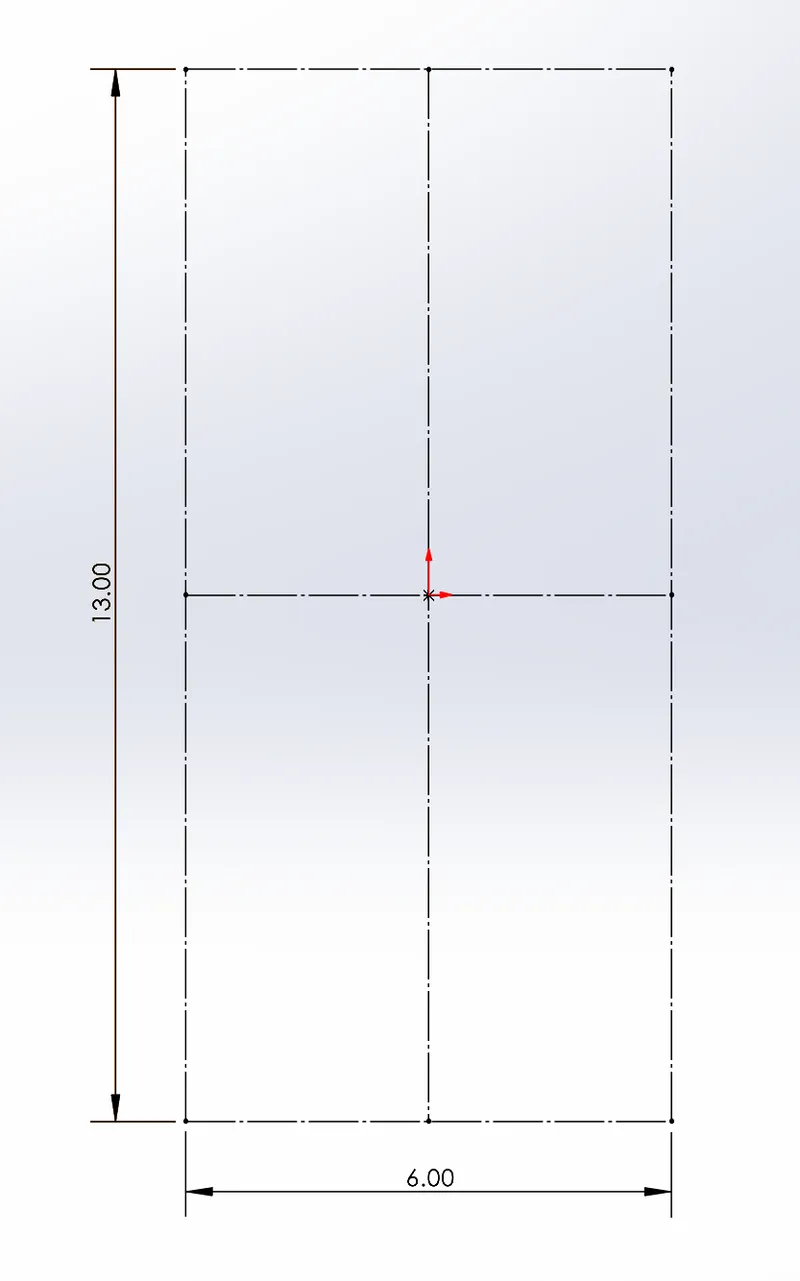
- Use the Center Rectangle Tool to create a rectangle with height 13.0 cm, length 6.0 cm CENTERED ON THE ORIGIN.
- Make sure that construction lines are from the midpoints of all the sides - Select the whole sketch, and mark it for construction using the checkbox labeled “for construction”
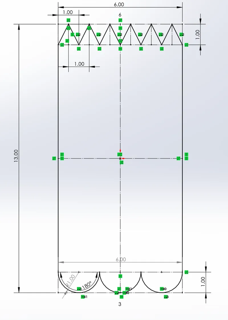
Creating Triangles on Top
- Use the line tool to create a HORIZONTAL construction line 1 cm below the top of the constraint box with endpoints on the vertical sides of the constraint box
- Use the smart dimensions tool to make the construction line 1 cm below the top of the constraint box
- We will refer to this line as Line 1 - Using the line tool, create a triangle with height 0.8 cm and base 1.0 cm, with the bottom left vertex coincident with the left endpoint of Line 1.
- Create 5 more triangles (does not matter if they are equal), each with 2 vertices on Line 1 and one vertex on the top of the constraint box
- The two triangles on the edge should each have 2 vertices touching the edges of the constraint box and 1 vertex touching another triangle - Click the bases of all the triangles, and use the equal relation to ensure they are all the same length.
- Mark the BASES and HEIGHTS of ALL THE TRIANGLES for construction
Notes:
Originally, we attempted to make the triangles using the linear sketch pattern tool, but changed our method when the points wouldn't line up properly.
Creating Arcs on Bottom
- Use the line tool to create a HORIZONTAL line 1 cm above the bottom of the constraint box with endpoints on the vertical sides of the constraint box
- Mark the line for construction
- We will refer to this line as Line 2 - Using the Three-Point-Arc tool, create one upside-down 180° arc with a radius of 1.0 cm
- The top left endpoint of the arc should be coincident with the intersection between Line 2 and the left side of the constraint box
- Its center point should be coincident with Line 2
- We will refer to this arc as Arc 1 - Using the Three-Point-Arc tool, create another upside-down 180° arc with radius of 1.0 cm
- Its top left endpoint should be coincident with the top right endpoint of Arc 1
- Its center point should be coincident with Line 2
- We will refer to this arc as Arc 2 - Using the Three-Point-Arc too, create one more upside-down 180° arc with radius of 1.0 cm
- Its top left endpoint should be coincident with the top right endpoint of Arc 2
- Its center point should be coincident with Line 2
- Its top right endpoint should BE TANGENT with the intersection of Line 2 and the right side of the constraint box - Make sure the 3 arcs are lined up evenly so the base of each arc covers 2.0 cm on the construction line on Line 2
Notes:
Similarly to creating the triangles, we originally used the linear sketch pattern tool to create the arcs, but also changed our method due to points not properly intersecting. Additionally, we originally attempted to line up the arcs using specific degrees and radii, but found that making the arcs tangent achieved better results.
Creating Sides
- Using the line tool, make two equal vertical lines connecting each endpoint of the horizontal constructions lines in Line 1 to their corresponding point that is directly below them in the construction line of Line 2
Creating Circles (eyes)
- Using the line tool, create a horizontal construction line 2.20 cm below the top of the constraint box with endpoints at the sides of the constraint box
- We will refer to this line as Line 3 - Using the circle tool, create a circle with a radius of 0.6 cm BELOW Line 3 and 1.71 cm away from the left vertical side of the constraint box
- Using the Tangent relation, make the circle tangent to Line 3 - Use the mirror entity tool to reflect the circle over the vertical line of symmetry
Notes:
Our original design set Line 3 at 2.5 cm below the top of the constraint box, and the circles were 1.70 cm away from the side of the box. However, after comparing our sketch to the original, we noticed that the eyes of our figure were slightly too high and slightly too wide, so we made these adjustments.
Creating Smile (Slots)
- Using the line tool, create a horizontal construction line 2.27 cm above the base of the constraint box.
- We will refer to this line as Line 4 - Using the line tool, create a horizontal construction line 1.8 cm above line 4
- We will refer to this line as Line 5 - Using the line tool, create a horizontal construction 3.9 cm above Line 5
- We will refer to this line as Line 6 - Create a vertical line 1.2 cm from the left side of the constraint box with endpoints on Lines 4 and 5.
- We will refer to this line as Line 7 - Using the mirror entities tool, mirror Line 7 over the vertical line of symmetry
- Using the 3 point arc tool, create an arc with endpoints at Line 4 and its reflected line, and middle point at the intersection of Line 4 and vertical line of symmetry
- Use the offset entities tool, put the distance as 0.6 cm, turn on reverse, and cap ends.
Notes:
These steps are the most different from our original design: our first sketch used only two construction lines, and the 3 point arc was the first component of the smile created. This resulted in very confusing use of the offset entities tool, and the unnecessary inclusion of additional arcs. The use of the mirror entities tool and cap ends feature was much a much simpler method to achieve our desired result.
Completed 2D sketch
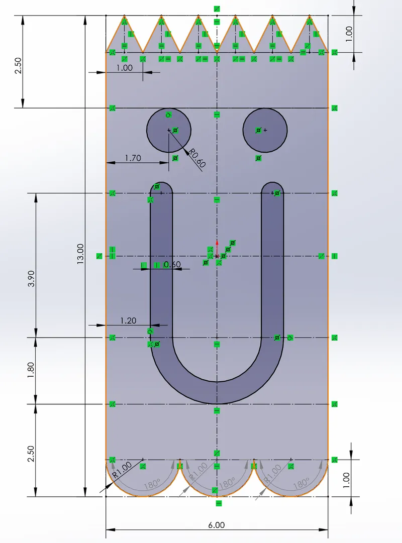
- When you are finished, you should see a “ghost” with triangles as hair, arcs on the bottom, two eyes, and a smile.
EXTRUSION
To make the sketch 3D, the boss extrude tool was used, and the sketch was extruded to be 0.10 cm thick.
ENGRAVING
To engrave the sketch, the Text Sketching tool was used 3 times (once for each letter), then the font of the letters was set to 1.00 cm and the letters were arranged in a vertical line.
The Extruded Cut tool was then used to cut the letters into the 3D model, with a thickness of 0.0495 cm.
Final notes:
Our design was almost a replica of the original, however, the triangles at the top of the clip were slightly too tall, resulting in the angles being different between the original and our designs. A future design would likely have triangles with a height of 0.6 cm instead of 0.8 cm.
Model origin
The author marked this model as their own original creation.


