Conductive Sample Holder For OpenFlexure Block Stage
Description
PDFOverview
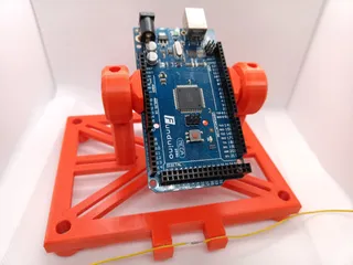
Developed to allow height probing of the RepRapMicron micron-scale 3D printer's build platform, this also allows conductive objects to be height-probed. The holder accepts a square of microscope slide and features a grounding contact. A conductive probe can then complete an electrical circuit with the object, indicating that it has reached the surface. This is known in CNC terms as “Z Touch” . The current RepRapMicron uses standard GRBL software for a RAMPS board, which uses the T2 connector for the touch probe.
Assembly
Before screwing to the OpenFlexure Block Stage, an M3 x 16mm screw is inserted from underneath and locked down tight with an M3 nut that fits in the top cavity. A small washer goes on the screw shaft, and a sprung solid copper wire ground probe is wrapped around it. A single coil turn gives the probe a lot more spring and flexibility. A second washer is secured on top with another nut. I've chosen to solder a jumper pin to the copper wire to allow easy disassembly, rather than directly solder the ground wire to the probe.
Use
A square of microscope slide is placed on the assembled stage between the prongs, the conductive sample goes on the slide, and the probe wire rests on it to provide anchoring and a return path for the conductive Z probe tip. See main illustration.
The G38.2 gcode command can be used to probe the Z height as per standard CNC operation. This has been successfully tested with the CNCjs app's probe function. The following python program can be used to generate gcode from a scanning grid, and the touch probe's XYZ position can be copied from the CNCjs serial console. From there it can be copied into a spreadsheet, graphing app etc.
Usability Hacks
As the coiled copper ground probe doesn't have much spring to it, materials that have a poor contact surface need a bit of extra push. I solved that by adding a strip of PET sheet drilled with a 3mm hole and screwed onto the ground post to add a bit of extra pressure.
Grid Gcode Generator
# probe_grid_gcode.py - Generate gcode to us Z probe to probe out a specified grid
def probe_grid_gcode(grid_size, line_spacing, safe_z_height, feed_rate):
gcode = []# Set initial position and safe Z height
gcode.append("G21 ; Set units to millimeters")
gcode.append("G90 ; Absolute positioning")# Calculate starting point (center of the grid)
start_x = -((grid_size - 1) * line_spacing) / 2
start_y = -((grid_size - 1) * line_spacing) / 2# Move along lines along X axis
for row in range(grid_size):
x_row = start_x + row * line_spacing
# Probe points along Y axis
for col in range(grid_size):
y = start_y + col * line_spacing
x = x_row
gcode.append("G1 Z{} F{} ; Move to safe Z height".format(safe_z_height, feed_rate))
gcode.append("G1 X{} Y{} F{} ; Move to point".format(x, y, feed_rate))
y = start_y + (grid_size - 1) * line_spacing
gcode.append("G38.2 Z-2 F{} ; Probe point".format(feed_rate))gcode.append("G0 Z{}".format(safe_z_height))
gcode.append("M2 ; End of program")return gcode
# Example usage
grid_size = 30 # ?x? grid
line_spacing = 0.05 # Distance between grid lines in mm
safe_z_height = 0.15 # Safe Z height in mm
feed_rate = 100 # Feed rate in mm/mingenerated_gcode = probe_grid_gcode(grid_size, line_spacing, safe_z_height, feed_rate)
for line in generated_gcode:
print(line)
Tags
Model origin
The author marked this model as their own original creation.


