Mostrom Print In Place Shaky Mountain Models (15, 20, 25, 30 [Degrees])
Description
PDFLesson Plan & Constraints:
The objective was to design and print a 3D-printed object derived from a simple-to-draw sketch of our choice.
- All designs must be made from an initial sketch, which are then to be offset numerous times, proceeding to follow a repeating process of extruded and cut so the designs would be a smaller version of the initial sketch
- Everything must fit within an 8x8 cm constraint box
- NO moving parts, (no gyroscopes, fidget spinners, etc)
Summary & General Advice:
My object consists of a simple mountain sketch that was offset 14 times, however the last 3 offsets were disregarded in order to make enough space for increased extrusion and cutting angles. I chose the mountain because I thought I would take my love of mountains and scenery and convert it into a personal project.
For anyone making their own mountain, using the offset tool to create different miniature subsets of your original sketch will not only speed up the process and make your time more efficient, but it will also make your project look much cooler.
Overview & Design Choices:
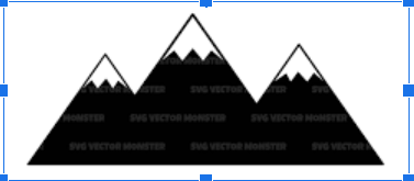
Before creating my shaky mountain, I did some google searching for inspiration. I finally came upon the sketch, and decided this was the perfect image to model my project off of. Down below is the image.
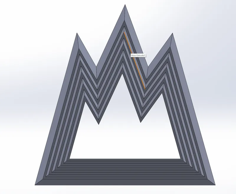
Below is what the sketch should look like after all the measurements and offsets are all set. The first thing that's really important is that you want to first draw the outside sketch within your 8x8 cm constraint box, and then use the smart dimension tool to adjust the length and angles of the lines before you then offset each sketch by 0.1 cm.
Some of the lengths and angles came out in awkward and complicated numbers, so I made sure to screenshot the exact measurements to be as precise as possible.
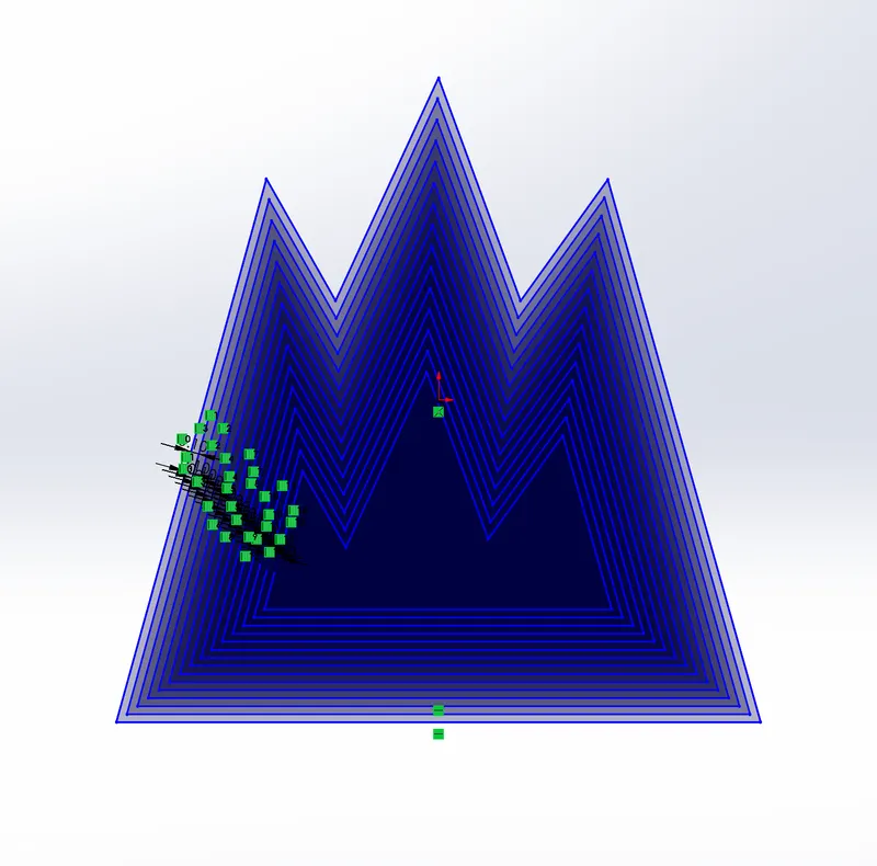
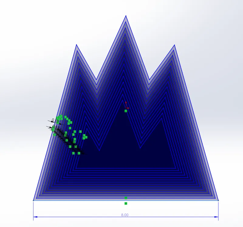
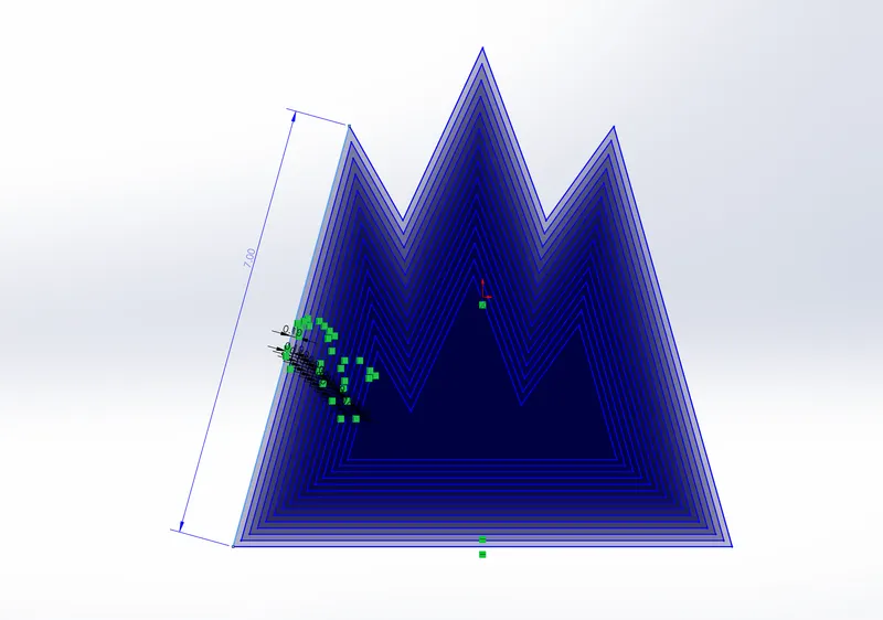
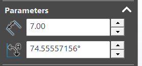
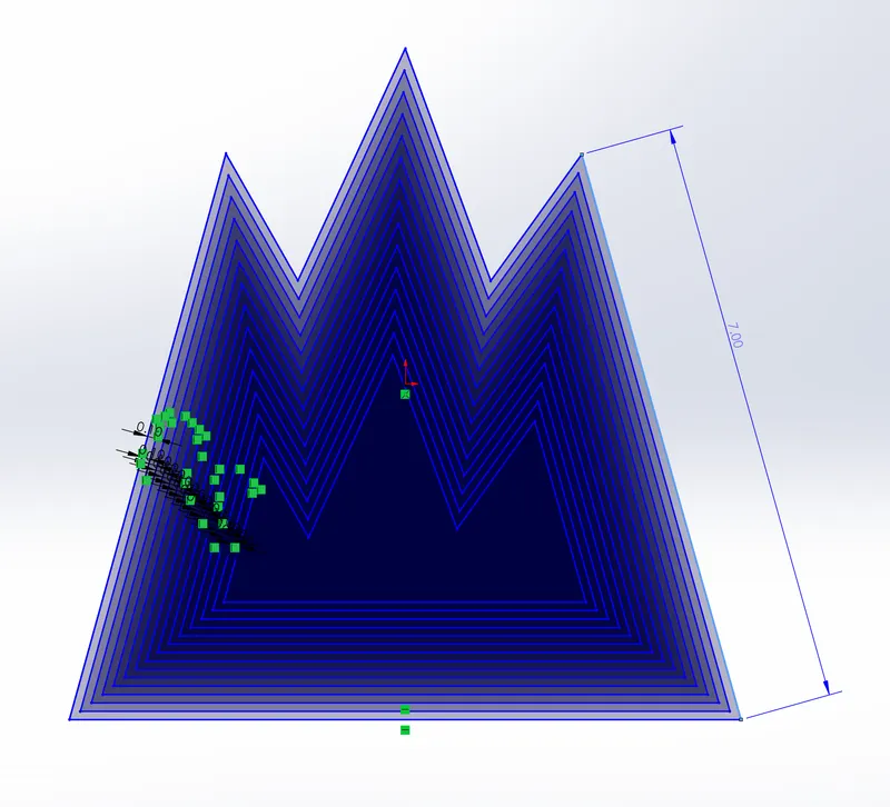
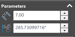
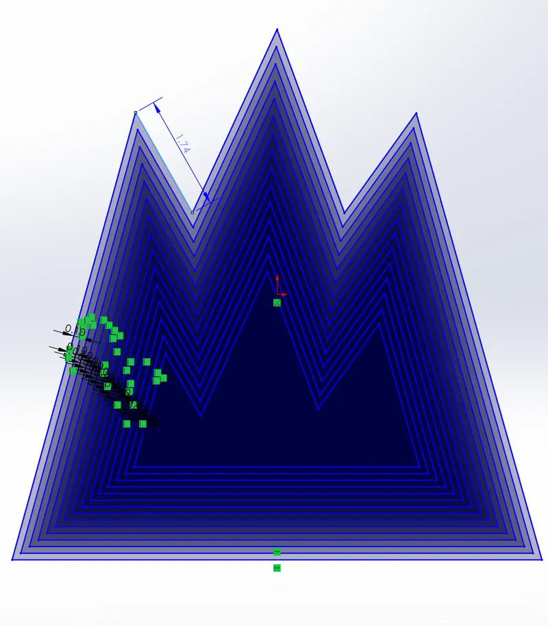
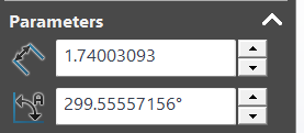
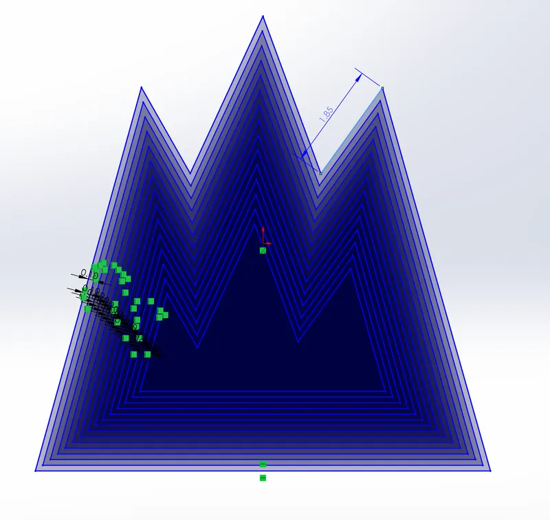
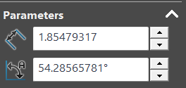
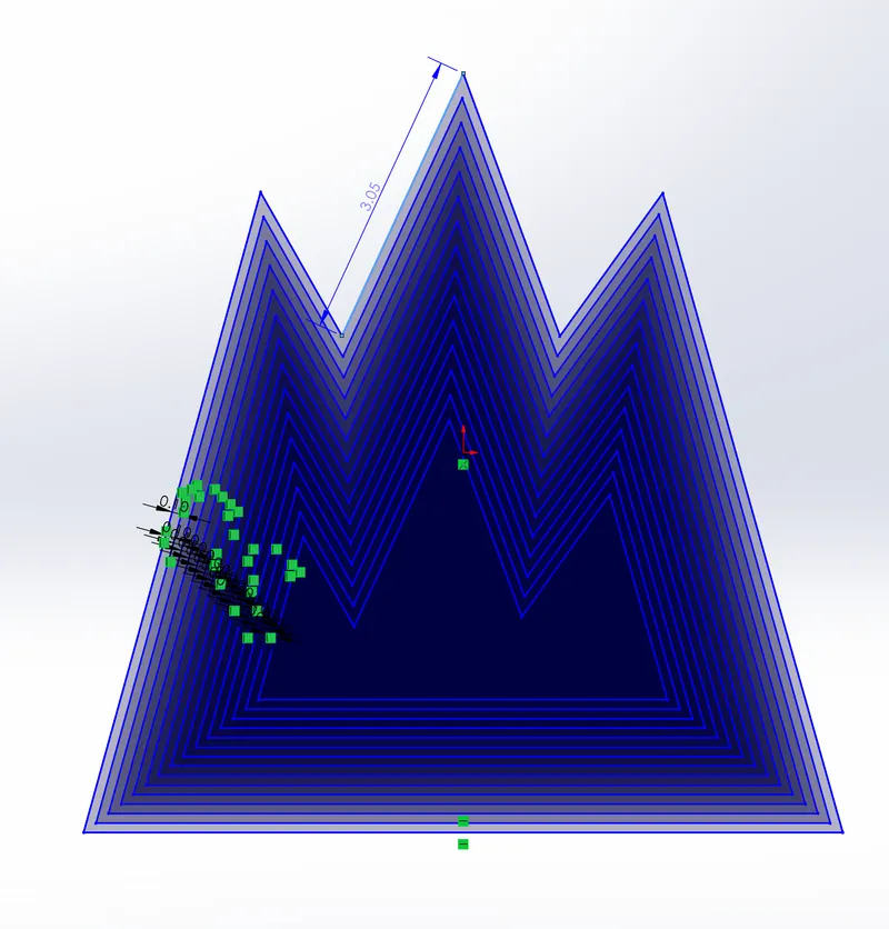
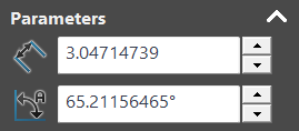
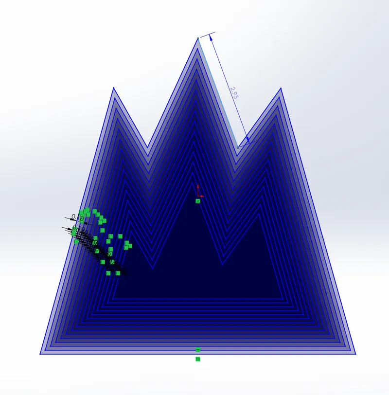
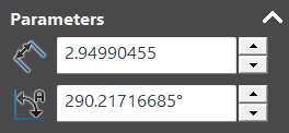
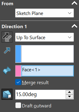
After all the measurements have been adjusted to the correct numbers, you then want to click the outside sketch and use the boss extrude command. Make sure the settings are set to what it says below (In this example I took screenshots of the 15 degree model, but for whatever number you use, make sure the extrude and cut angles are the same).
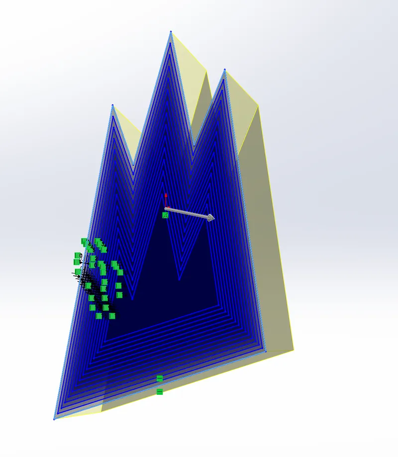
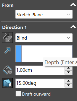
Next, you want to click the line after the line that has been extruded, and you will use the extruded cut command. Make sure that the direction of the arrow is reversed so that the cutting can go smoothly. You do not need to re-change the direction when you use the extrude command because it will auto-correct itself back to its original position. For this specific model, the cut angle will match the extrude angle (15 degrees in this case).
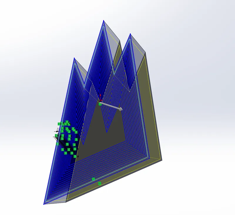
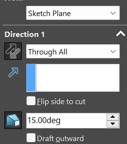
The reason why I took an extra screenshot of the extrude command is because for the first extrude, the direction will be selected as “Blind”. However, after the first extrude, every single other extruded direction will change to “Up To Surface”. Simply after clicking this, Solidworks will ask you to click a surface, and you will respond by clicking the surface of the outer original sketch. All cut directions will be the same as well, selected as “ Through All”.
Make a total of 6 extrudes and 6 cuts.
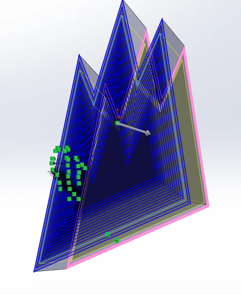
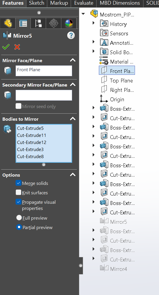
After all the extrudes and cuts have been made, you then want to click on the mirror entities tool and select the feature manager tree, which should highlight the entire object like down below, which should show up in the “Bodies to Mirror” section. Make sure that you check the boxes “Merge solids”, “Propagate visual properties”, and “Partial preview”.
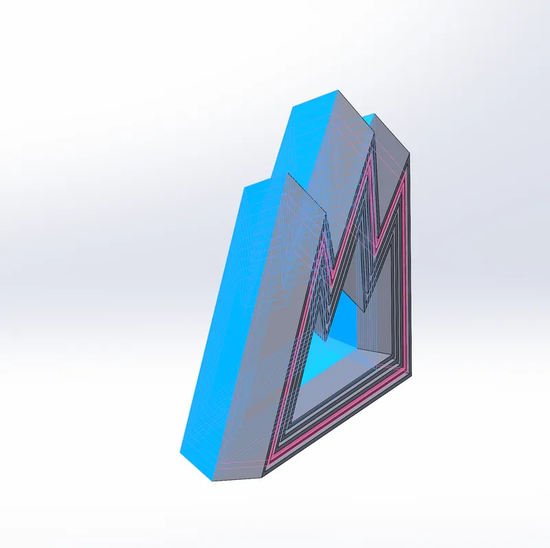
This should be what the final product looks like. To move on to the next angle variation, you want to save the current file by clicking “File” at the top of your computer screen and dropping down to “Save as”. I named this one “Mostrom_PIP_15” and changed it into a .3mf file. Now you can save the file and change the degrees for future variations without having to worry about the previous model losing progress or having the angles rearranged.
After all 4 different models have been saved, they are now ready to print!
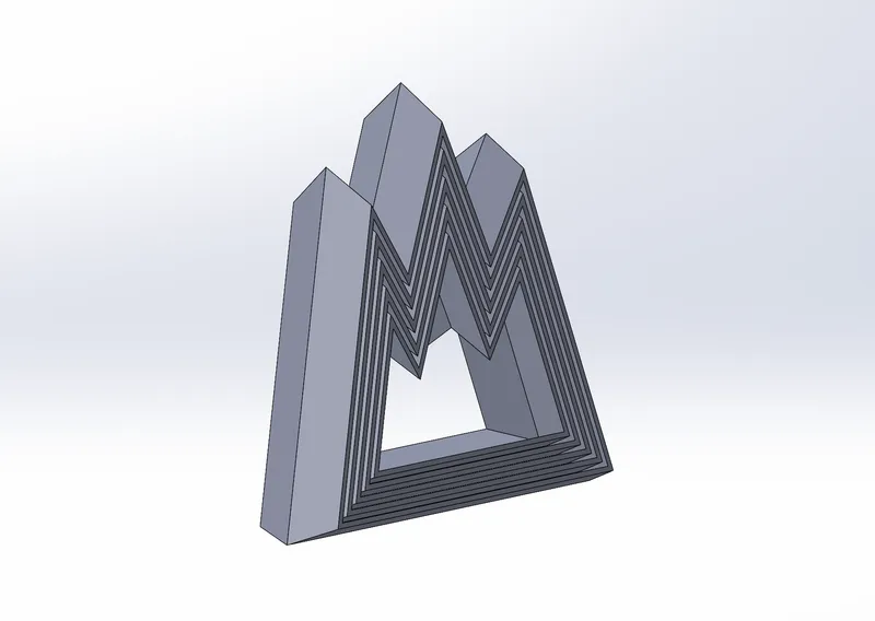

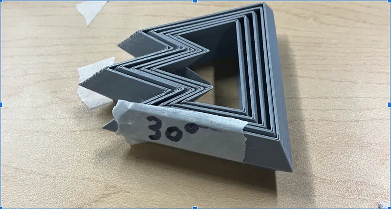
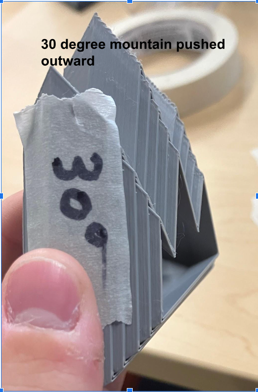
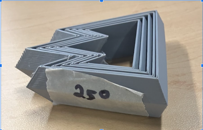
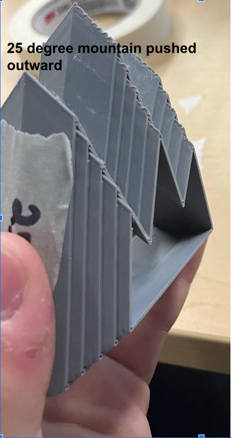
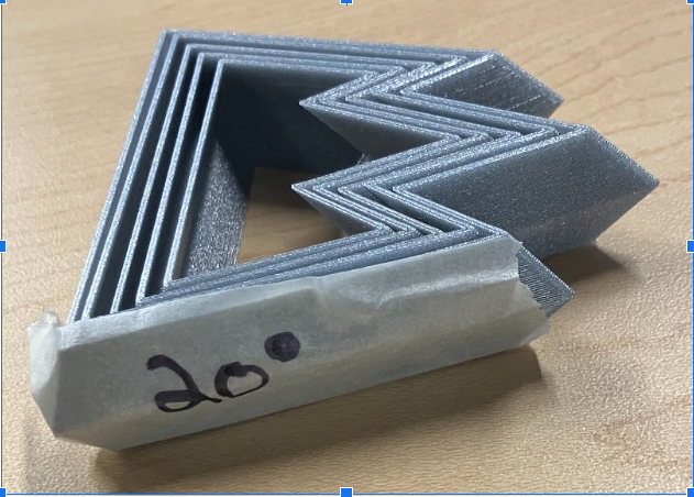
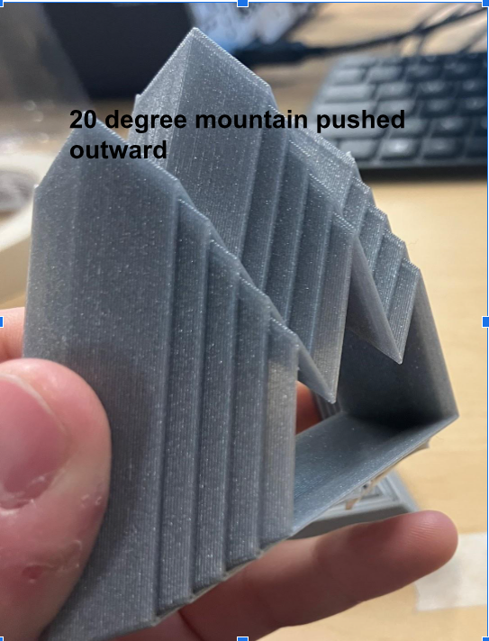
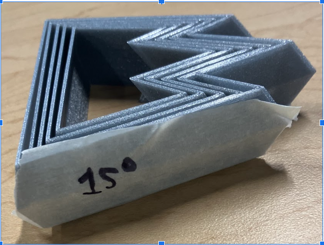
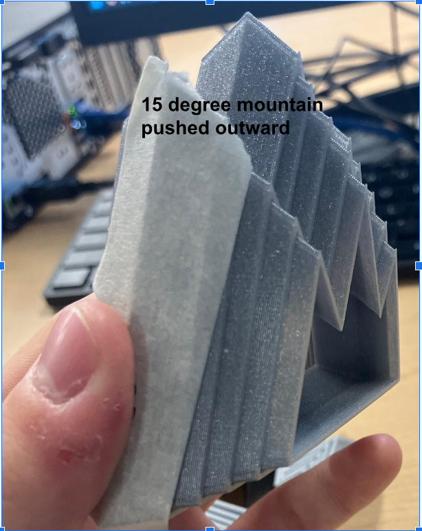
The 4 models came out really well, and I labeled them on the side by their extruded and cut angles. I took each model and pushed it out from both sides, and it may be a little hard to see through the pictures, but it seemed that the lowest angle had the most ease and distance to fluctuate and be flexible, meaning angle degrees and object fluctuation are inversely proportional with each other.
These are the official final products, enjoy!
Model origin
The author marked this model as their own original creation.
