Core XZ Anet AM8 Conversion

Description
PDFCore XZ Anet AM8 Conversion:
There is now revision 6 uploaded (see in the update section)
This is a design to convert an anet a8 or other i3 cloes into a Core XZ printer. It is an upgrade on top of the AM8 upgrade (https://www.thingiverse.com/thing:2263216) by pheneeny.
The parts will probably also work with an ender e3 and other bedslingers which have an aluminium extrusion frame, but might need some adaptions since the AM8 extrusions are sligthly different.
The main goal of this design was a CoreXZ conversion while staying reasonably cheap an quiet. That's also the reason why the X-Axis is done with V-rolls. Cheap linear rails would be much louder here. For the Z-Axis the cheap MGN12H should be no issue since they only move slow. If you want to go full linear rails, you should look into the voron switchwire conversion.
This Upgrade consists mainly from 3 units:
XZ Axis:
This part contains the normal Z frame of the Anet AM8 and an additional 433mm V-slot 2020 estrusion for the X Axis. The beltpath parts are remixes of the voron switchwire parts. The biggest difference to the switchwire is are already mentioned the V-rolls running the X-axis. Sure you could go with the linear rail which could make the X-carriege smaller and stronger but the V-rolls will also work out very well if they are pretensioned correctly. And they will be less noisy.
All parts are designed in a waythat allows you to scale both axis if you use longer extrusions. You just need to adjust the belt and rail lengths.
XZ Motors:
Directly mounting the Motors to the belts has the issue that the X Axis will move down by itself because of the weight if they are not powered on. Therefore the solution is to have an additional transmission behind the motor. It's the same concept as the Z axis of the Voron 2.4. Since this is a core xz build, the belts have to move faster than with the voron. But the weight of the Axis ia also way lower. Because of this a Transmission of 20T to 36T was choosen. That should allow high speeds with nice resolution but still prevent the axis from moving by gravity.
In the case that this is too low there is more place for up to 60T Gt2 pulleys. Also the 20T pulley could be changed against a 16T pulley.
The motor can be moved to tension the closed belt in the transmission. The whole Motor-Transmission unit can be moved downwards to tension the XZ belts aswell.
X Carriage:
The X-carriage Design is for a combination of the sherpa mini extruder by annex engineering and the NF Crazy (mosquito hotend clone). Its main job is pretentioning the V-rollers. This is done by 4 screws from the bottom which press the rolls against the extrusion. This can be done by directly clamping both carriage parts together with the screws or using some spring loaded screws if you find some small springs (same concept as many CPU coolers). Hotend cooling is done with a simple 4010 axial fan and part cooling is done with a 5015 radial fan.
Update:
I uploaded now revision 6. Main part is the improved gearbox. The whole tension part changed. The bolts now don't go through the whole box but into heatinserts at the bottom. I also added bolts at the side to help make it stiffer after tensioning. For easier access there is now also a big opening in the top that can be closed with a easy removable cover. The Motor mounting also showed too much flex in the past and is now improved. The part cooling duct was also changed a bit. But that is only a vissible change and not neccassary for the function. I also uploaded a x-endstop mount and a bl-touch-mounting bracket.
Following parts are changed or new :
- The complete gearboxes (Cover, Upper and lower housing, Motor mount)
- bl-touch mounting bracket
- x-endstop mount
- Part cooling duct
Mechanical parts needed:
Only parts which are additional to the AM8 design
XZ Axis:
- 2x 1800mm GT2 6mm belt (needs adjustment if you go with a bigger frame)
- 2x MGN12H 430mm Linear rails (for 500mm Z-Extrusions. Adjust the length for different heigth)
- 413mm V-slot 2020 Extrusion
- 16x F695 2RS bearings
- 18x M5 T-nut for 5mm slot
- 2x M5 melt inserts
- Screws:
- 6x M5x30 screws
- 18x M5x10 screws (button head preferred)
- 8x M3x10 screws
XZ Motors:
- 2x Nema 17 Motors (use the standard anet a8 motors. For an upgrade you can go with OMC 17HS15-1504S1 or LDO42TH48-2504AC Motors)
- 4x GT2 20T Pulley (5mm hole; 6mm wide belt)
- 2x GT2 36T Pulley; 5mm hole; 6mm wide belt (for different transmission change this
- GT2 closed loop belt 110mm length , 6mm wide (changes with different pulley sizes)
- 4x 625 2Z bearings
- 8x M3 brass melt-inserts
- 2x M5 nuts (nylock preferred)
- 2x M5 T-Nuts
- 8x M3 nuts
- Screws:
- 2x M5x50 screws
- 2x M5x10 screws
- 8x M3x30 screws
- 8x M3x25 screws
- 8x M3x12 screws
X Carriage:
- 3 V-rolls ( Outer diameter 24mm, inner diameter 5mm, Thickness 11mm → standard CR10 replacement rolls)
- NF Crazy hotend (or other mosquito style hotends / or slice engineering Mosquito)
- Sherpa mini Extruder (designed by annex engineering )
- 1x 5015 fan (dual ball bearings preferred)
- 1x 4010 fan
- 30mm PTFE D4
- 25x M3 brass melt-inserts
- 3x M5 brass melt-inserts
- Screws:
- 3x M5x35 screws
- 2x M3x20 screws
- 1x M3x15 screws
- 3x M3x12 screws
- 3x M3x6 screws
- 1x M2x10 screws
Print instructions:
- No supports (all parts should be printable without supports)
- 0.4mm line thickness
- 0.2-0.25mm Layer height
- 3 perimeters (4 perimeters for structural frame parts)
- 5 top/5 bottom layers
- 20% infill (30% for structural frame parts)
- Most Parts should work with any material you want.
- X-carriage and Motor mounts should be from ASA or ABS since the temperatures here might rise depending on your print behavior.
- Some stepped holes have the lowest section closed for better bridging. You need to open that single layer adter printing for the screws.
Assembly instuctions:
I won't explain every detail here, since if you build it you'll know that printer well enough for that. Also you can look up details in the 3d Models.
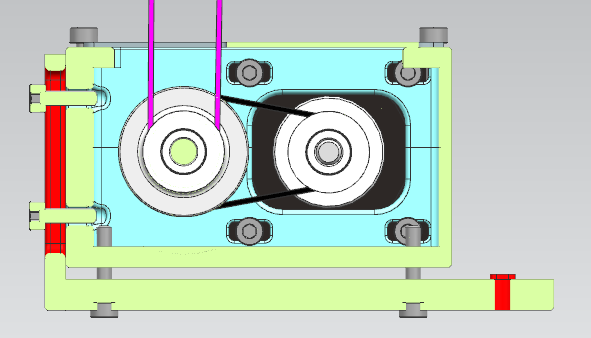
The belt paths are as shown in following pictures:


The belt idlers are made with 2 695 bearings each. You can also use the normal idlers aswell but the ones with the bearings have proven to be more reliable for me in the past:

Between those bearing stacks are 2 M5 washers as shims. The Axis of the bearing are simple M5 bolts.
The more interesting part might be the belt tensioning and clamping. The belt ends will be clamped a the x- carriage with the 2 printed clamps at the bottom:

Afterwards you can tension the belts seperatly with the 2 motor units. As you can see in the following picture there are m3 screws in the bottom of the motor unit. The M3 screws (left side of the transmission) need to be loose first. They you can pull the whole motor unit evenly down by scewing the M3 in the bottom. That will allow to tension the XZ axis very fine.
You need to melt in inserts into the bottom and the side where those bolts go into. It would be best to melt them from inside. That way they hold better if you tension the motor.
Also visible in the picture are the motor mounting bolts. These are in slot holes which means the motor can be moved. The small 110mm closed belt can be tensioned this way. Make sure to do this before you mount the Transmission unit to the printer. Otherwise you cant reach them.
A M5x50 bolt will act as axis for the larger belt idler. You can secure it on the back with a Nyloc nut to keep it in pace (I'm not sure if it wouldn't move without that, because the thread may move it a bit axially. ). But it should still work without that nut since the pulleys act a bit like nuts (there could still be a bit play left).
The X-carriage with the 3 V-rolls can be adjusted by the 4 screws in the bottom. An additional idea would be to add spings under the screw heads for some special pretensioning.

The cooling duct can be slightly adjusted in Z-direction. It has an additional mounting point in the front behind the hotend for a m2 screw. You can use this if the cooling duct is moving too much.
The hotend is held in place with M2.5 screws from the top (should be included with the hotend). You an only reach them when the extruder is not mounted. The Sherpa mini extruder can be mounted with all 3 mounting holes which are possible by design. But the two from the top will also be enought if you don't have the front mounting.
Between the hotend and extruder you need to place a 30mm PTFE piece (OD=4mm) which connects both parts and keeps a constrained filament path.
Many components are also connected with melt inserts. Those metal threads can be melted into the plastic and allow strong connections. Following pictures show where those are used.
You can see them as orange circles around the holes:


The brass inserts left and right side of the hotend are there for additional stuff like bed probes, endstops e.g if you want to use this. If not needed you can also leave them away and save a few gramm.
The printer is overall intended to be used with a bed probe as Z-Endstop. Therefore no Z-Endstop mount was designed. If needed it should probably work out to use the AM8 endstop and mountit on the back side. The X endstop is a simple switch mounted on the lower side of the V-rail extrusion between the belts and the profile. The endstop mount can be mounted with a single m3 screw. The endstop is triggered by the carriage body. You can move the endstop mount in any x position this way.

NOTE: Cable chain attachments for all axis will also follow in the future.
Possible Errrors and Solutions:
Here is a list of Problems which occured during assembly and the solutions against it.
- Z moving unintended when X is moved. → Make sure you use the correct belt. There was an issue where the gears were GT2 but the belt was more like GT3. This lead to issues.
- Z and X wobeling a bit why the other Axis was moved. → If the Motor Mounts were not printed stiff enougth or from the wrong material, the whole geatbox can woble around. PETG wasn't stiff enougth in my tests. ABS with 3 wall lines and 4 top and Bottom worked fine. Also the V2 Gearbox and mounts improved this issue.
Tags
Model origin
The author hasn't provided the model origin yet.


