VELORA 3D PRINTED RC AIRPLANE WING [TEST PIECE]
Description
PDFFINAL VERSION LINK
Link to build plate adhesive that I use for reliable printing:
PLEASE LEAVE A COMMENT IF YOU HAVE A QUESTION OR IDEA FOR IMPROVEMENT.
NOTES
CG is marked on bottom of plane with an inset circle. In my experience, this CG location requires a tiny bit of up elevator to fly level. Feedback from first tester indicates that this CG is a neutral position and they preferred a slightly more forward CG. I will leave it as is.
MOTOR MOUNT has been updated for 16mm spacing drone motors.
SPECS
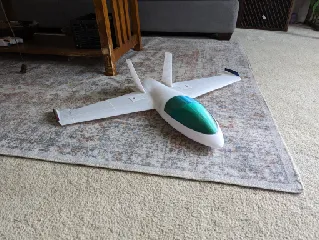
- Wingspan: 820mm
- Weight:~1kg
- Length: 540mm
HARDWARE
- Magnets:
- 4 * 8mmx3mm magnets for hatches
- Screws:
- 2 * M3 x 12 - 16mm screws for holding in the motor mount
- 8 * M2 Screws for holding in the servo hatch
- Filament:
- TPU for hinges
- PLA+ [~600g]
- Motor: T-Motor F80 PRO 2200kv
- ESC: 40 amp
- Propeller: 6 x 4
- Battery: 4S
- Flight Controller [not required]: Speedybee f405 mini with gps or equivalent
- Servos: 9g servos [SG90] NOTE: I have heard people commonly use EMAX ES08 servos and will look into the dimensions to add alternate mounting for those.
Printing Settings:
!!Use brim for all larger parts, lifting up even a small amount will create parts that are hard to combine cleanly!!
!!Zhop is highly recommended for tall parts to decrease the likelihood of knocking them over!!
- Starting Point for Settings:
- 0.4mm wall with 1 perimeter
- 3 layers, top and bottom
- 0.25mm layer height
- 0% infill
- Additional Part Specific Settings:
- For WING 1
- You will need support for the top of the servo tray area, I recommend Hybrid Tree Supports.
- For Tail Fin and Tail Fin Mount:
- Increase to 2 perimeters
- For Wing Tip:
- Change to 0.16mm layer height, to allow for curvature
- For Fuselage 3 and 4:
- Add 6% gyroid infill with 0mm to 2mm Maximum Length of Sparse Infill Anchor (lowers weight)
- For Motor Mount:
- Change to 4 perimeters minimum and 15% infill minimum. Possible to use PETG here for increased heat resistance.
- For Servo Covers:
- Increase to 3 perimeters and 10% infill.
- Control Horns:
- Increase to 4 perimeters and 100% infill
- Change to 0.16mm layer height
- For Body Spar Support:
- 4 perimeters and 20% infill
- For Spar:
- 6 perimeters and 15% infill
- For Hinges:
- Print using TPU settings 100%infill, probably just a few layers thick
- For Connectors:
- Print out of PLA with 100% infill [same file as hinges]
- For WING 1
Tags
Model origin
The author marked this model as their own original creation.


