Prusa XL Z Banding Fix


Description
PDFWatch the accompanying video:
Join me on Patreon (behind the scenes content & 3D models): https://patreon.com/user?u=80746241
Buy me a coffee/beer: https://ko-fi.com/ygk3d
Instructions for Testing:
For 5 tool machines:
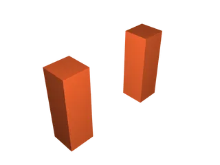
1. Print PrusaXL-5-Head-Toolchanging-Banding-Test.3MF.
2. Observe layer quality. If banding is observed, proceed to step 3.
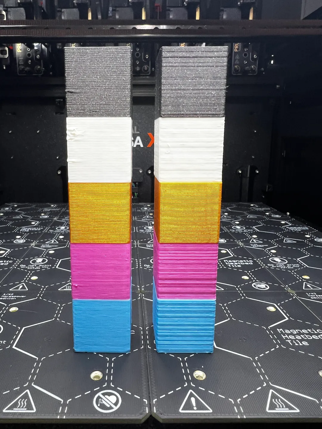
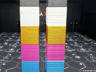
3. Optionally: Print PrusaXL-2-Head-Toolchanging-Banding-Test.3MF - This can be used to compare layer quality with and without tool changing for each tool individually. Choose which two tools you'd like to evaluate and print the model. Inspect top two cubes and compare to bottom two cubes to see how layer quality changes with tool changing.
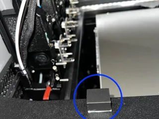
4. Print PrusaXL-Bump-Block v3.STL
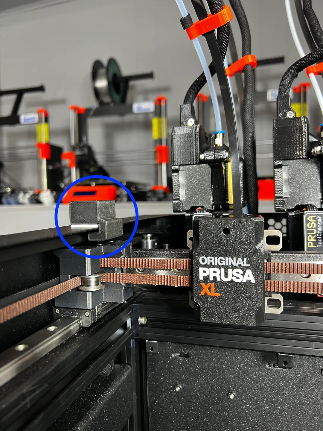
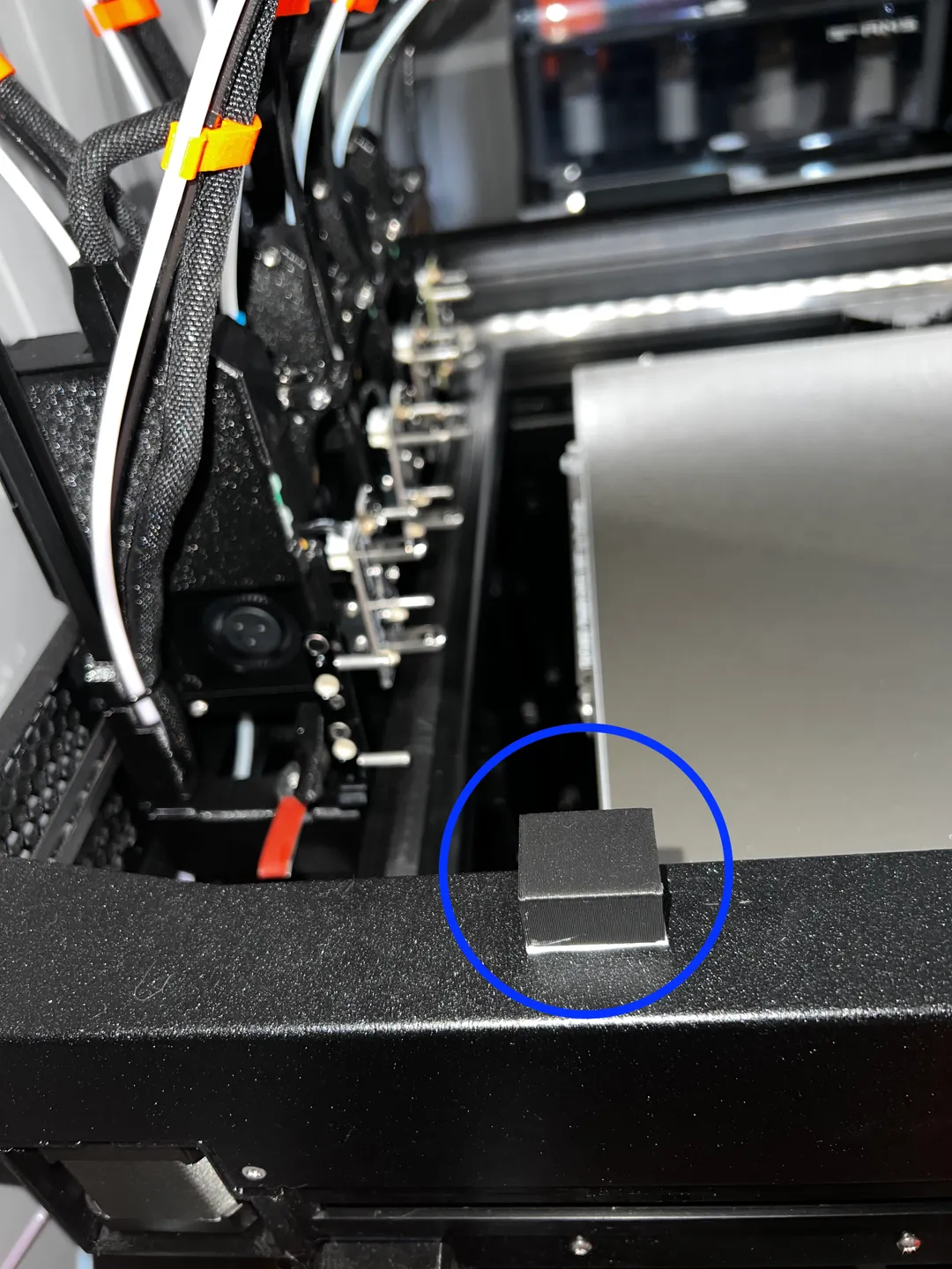
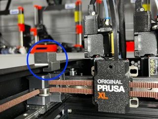
5. Apply adhesive mounting square to underside of block and install on rear left of printer frame (see photo).
6. Print PrusaXL-5-Head-Toolchanging-Banding-Test-With-Bump.3MF and observe how layer quality changed from the first test. If layer quality is improved, proceed to step 7.
7. Add the following two lines of G-Code to your "Tool change G-code" under Printer Settings > Custom G-Code in PrusaSlicer:
G0 X3 F5000
G0 X0 F1000
8. Save modified printer profile for future use.
For 2 tool machines:
1. Print PrusaXL-2-Head-Toolchanging-Banding-Test.3MF
2. Inspect top two cubes and compare to bottom two cubes to see how layer quality changes when tool changing. If layer quality is considerably worse when tool changing, proceed to step 3.
3. Print PrusaXL-Bump-Block v3.STL
4. Apply adhesive mounting square to underside of block and install on rear left of printer frame (see photo).
5. Print PrusaXL-2-Head-Toolchanging-Banding-Test-With-Bump.3MF and observe how layer quality changed from the first test. If layer quality is improved, proceed to step 6.
6. Add the following two lines of G-Code to your "Tool change G-code" under Printer Settings > Custom G-Code in PrusaSlicer:
G0 X3 F5000
G0 X0 F1000
7. Save modified printer profile for future use.
NOTE: The bump block should go on the top frame of the printer, on the left hand side, approximately centred with the rear of the bed.
OTHER IMPORTANT INFORMATION:
- If you still have banding after applying this fix, you may need to push the tool further into the bump block. You can try changing the second line of the bump g-code to: G0 X-1 F1000.
- It's important to ensure that the wide flat part of the tool can overlap the bump block. If your adhesive is too thick, it will hit it prematurely, causing a crash event.
- If the tool can overlap the bump block and you're still getting crash events, try adjusting the X coordinate of the bump (i.e. change X0 to X1). You can also try reducing the crash sensitivity on the LCD.
- Occasionally the printer will attempt a “precision adjustment” (usually after an idle period) in the back left corner. The bump block will cause this to fail and the printer will restart.
Tags
Model origin
The author marked this model as their own original creation.