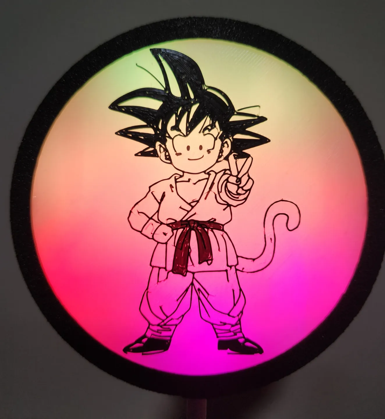
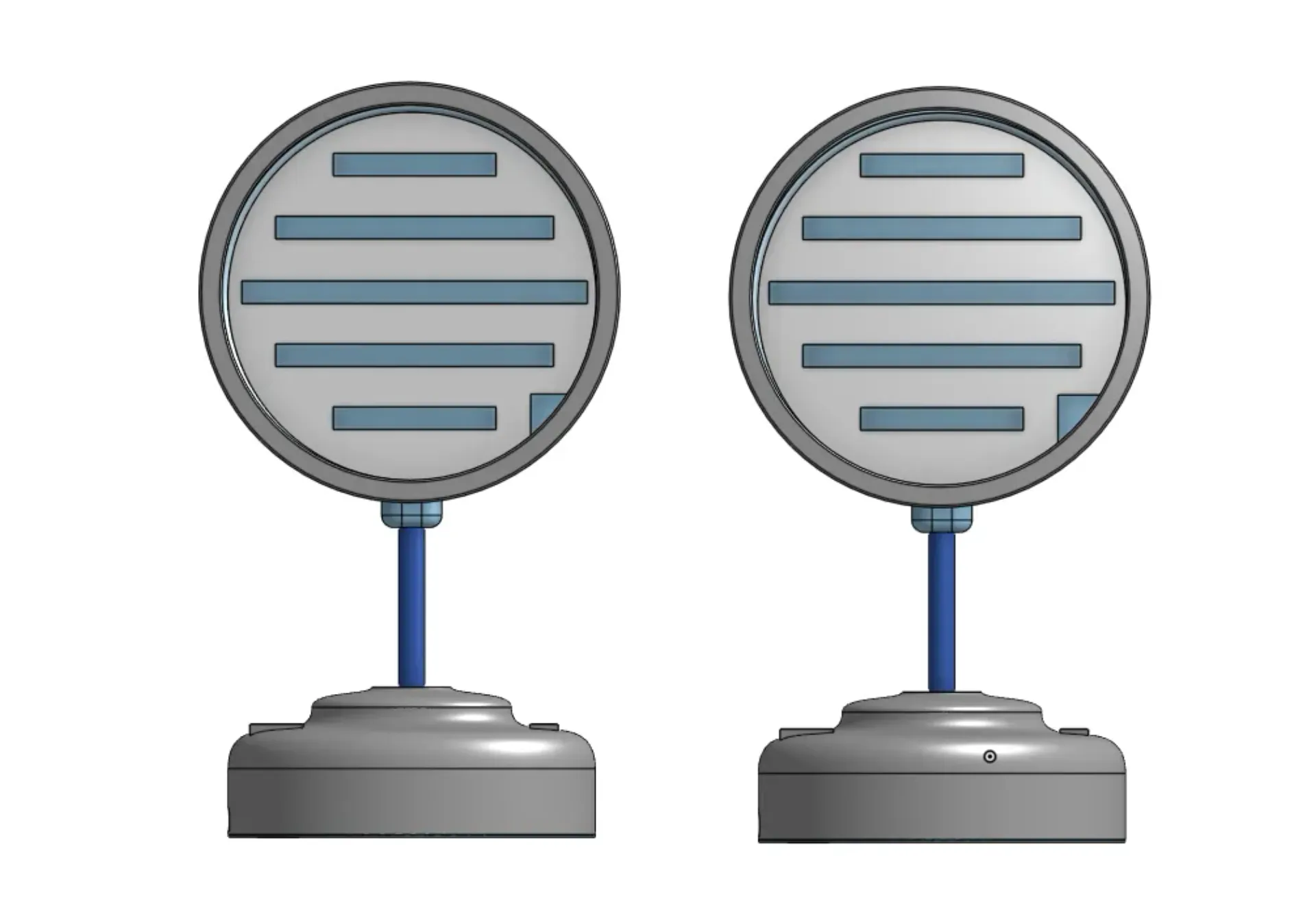
Neopixel Desk Lamp Display (with removable lens)


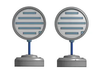


Description
PDFThis desk lamp is designed with WS2812b (neopixels https://www.amazon.com/ ) any LED density will work, but you could use RGBs if you want.
I designed the bases to use ATTINY85s. https://www.amazon.com/ (The base with a battery can fit either model of the Attiny85s)
The version with the battery uses any 3.7 lipo battery ( I used these https://www.amazon.com/), and a lipo charger with battery protection https://www.amazon.com/ (either type-c or micro-usb)
I made a stem for the model to print or you can use PTFE tube https://www.amazon.com/ or metal tubing https://www.amazon.com/ , just cut to desired length.
The power switch I used was https://www.amazon.com/
There are 2 models one that uses a 2 position switch ( for brightness) https://www.amazon.com/ and a 3 position switch ( for brightness and pausing effect) https://www.amazon.com/
OTHER STUFF NEEDED
- Wire https://www.amazon.com/
- Solder and solder gun https://www.amazon.com/ (use a fume extractor for your safety https://www.amazon.com/)
- 300-600 Ohm resistor https://www.amazon.com/
- Black and White filament (your preference) PLA will kinda melt if you leave it in your car FYI. https://www.amazon.com/ (PLA) https://www.amazon.com/(PETG)
- A computer to program using Arduino IDE https://www.amazon.com/ ; )
- Hot glue and hot glue gun https://www.amazon.com/
- Micro USB cord to program and power ATTINY85 or battery charger ( Or Type-C if you go that route for the battery charger. The Attiny85 uses micro-usb.) https://www.amazon.com/
- Super glue https://www.amazon.com/
- 3d Printer (Just buy them all)
HOW TO BUILD
- Print desired design, with or without a battery Light Base Bottom and 2 or 3 position switch Light Base. Both the Light Case and Light Base will need support (on the build plate only).
- Program Attiny85 (instructions and code further down)
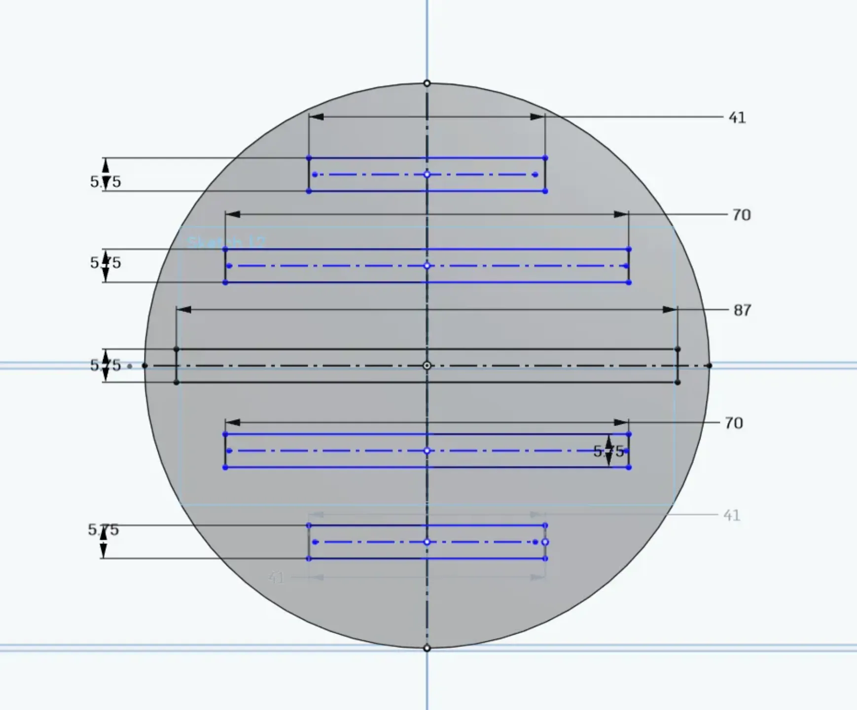
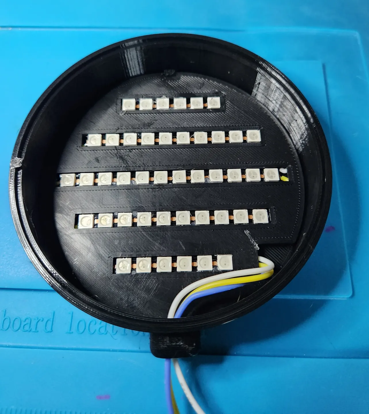
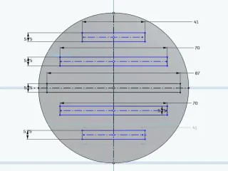
- Cut led strips so the pixels fit into cut out of the LED Plate. 2x- 41mm 2x-70mm 1x-87mm ( max width for the pixels, not the strip strip itself.

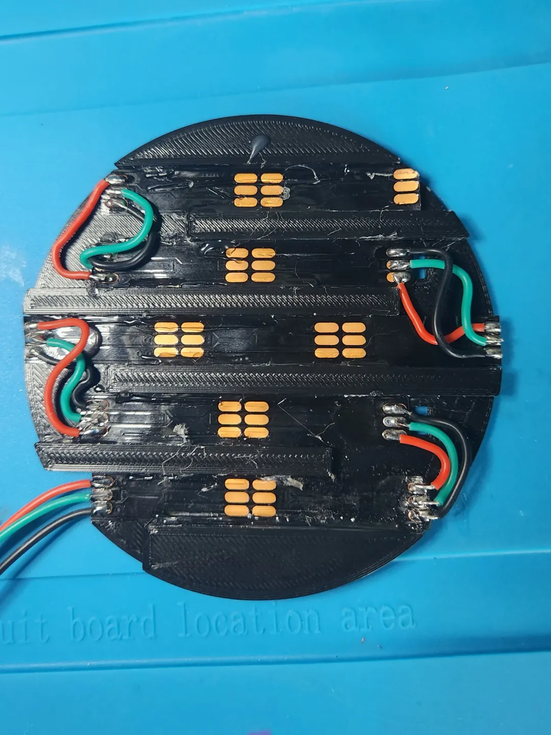
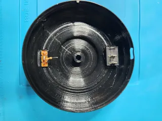
- Pre-solder the strip ends then hot glue them into the correct orientation as shown below. (follow the arrows)

- Cut and solder on wires. (Have fun, its the most difficult part, but it's not too bad. Just give yourself a long enough tail for soldering the Attiny85. It's easy to cut off some extra wire, it's a pain to try to add more wire to a too short wire )

- Place LED Plate into the Light Case and hot glue all around the edge then (carefully without burning yourself) press down the LED Plate Cover.


- Thread the wire through your Light Case and Stem.
- Super glue the Stem, PTFE tube, or steel tube to the Light Case. Set aside and let dry.
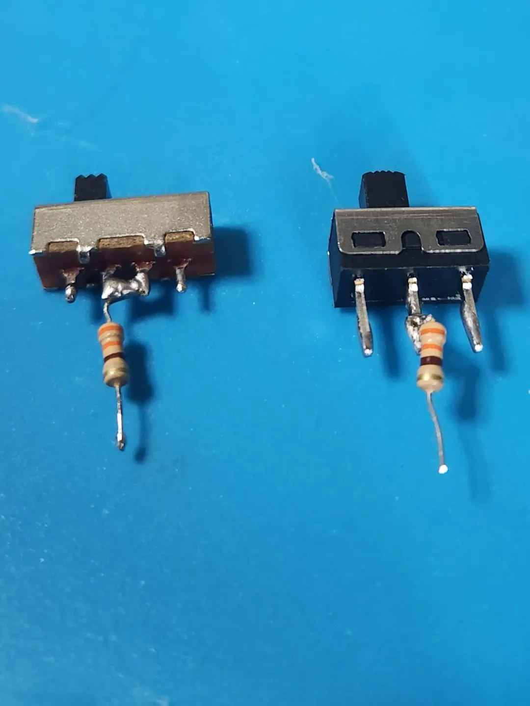
- Pre-solder position switch (solder 300-500 ohm resistor to middle pin/s) and power switches, place in Light Base and hot glue to secure.


- Thread wires into Light Base and super glue the Stem in place.
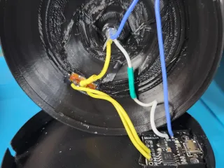
- Solder the LED data line (green or yellow in pics) to the resistor, then solder 2 wires to the other 2 switch pins. Solder those wires to pins 3 and 4 of the Attiny85.

- Wire Power (see below)….
- Hot glue wire connections (for stress relief and strength)
- Snap on bottom, it only fits 1 way. (watch your fingers, It's easiest if you place the Light Base Bottom flat on a table and push the Light base on firmly)
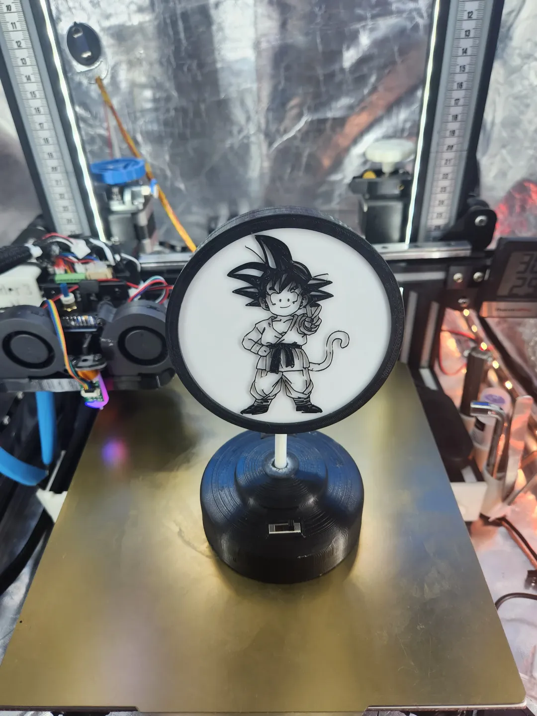
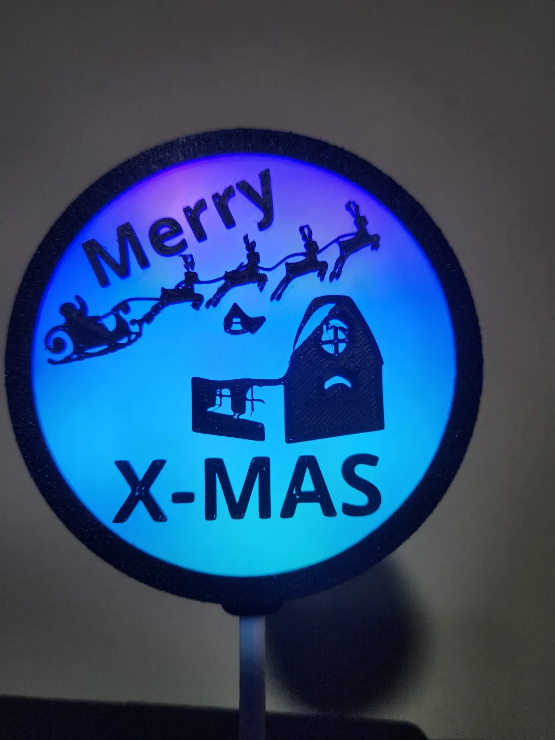
- Print and place in your favorite lens, snap on the Light Case Lid, power on and let you friends be jealous of your ingenuity.
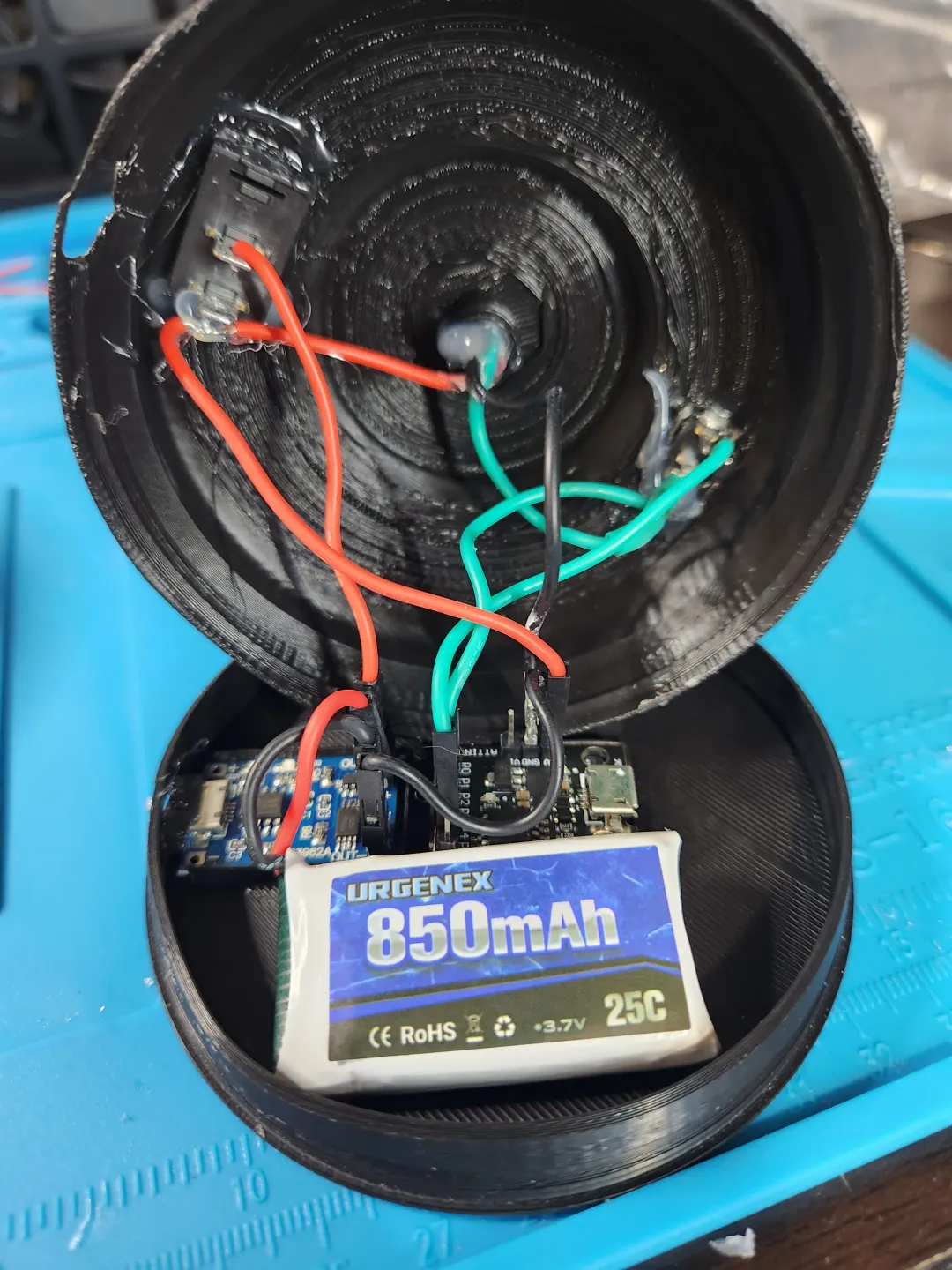
WIRING POWER (with Battery)

- Solder the LED power line (red or blue in pics) to a leg of the power switch
- Solder A new wire on the same leg to the “5v” pin on the Attiny85
- Solder the LED ground line (black or white in pics) to the “GND” pin on the Attiny85 (strip a nice length of wire, because you will have to solder another ground from the battery charger to it as well)
- Solder new power and ground wires to the “OUT” pins of the battery charger. The power line gets soldered to the free leg of the power switch, and the ground gets soldered together with the LED's ground connection on the Attiny85's “GND” pin
- Now for the battery, DO NOT CUT BOTH WIRES AT ONCE!!! Switch power switch off “o”
- Cut and strip the battery's ground wire (black) then solder it to the “B-” of the battery charger
- Cut and strip the battery's power wire (red) then solder it to the “B+” of the battery charger
- Hot glue battery charger, battery, and Attiny85 into place.
- Continue to step 14 of HOW TO BUILD
WIRING POWER (without Battery)
- Solder the LED power line (red or blue in pics) to a leg of the power switch
- Solder A new wire on the same leg to the “5v” pin on the Attiny85
- Solder the LED ground line (black or white in pics) to the “GND” pin on the Attiny85
- Hot glue Attiny85 into place.
- Continue to step 14 of HOW TO BUILD
PROGRAMING THE ATTINY85
You'll need to download Arduino IDE https://www.arduino.cc/en/software . Once you have it installed you'll need to add 2 libraries to the adruino IDE program. The Adafruit Neopixel Library and Digistump Library (http://digistump.com/package_digistump_index.json)
Here is my code I used, just edit the number of LEDs so it matches what you used. To program the Attiny85 make sure you have the 2 Arduino libraries. Simply add the code, chose board: Digispark (Default - 16.5mhz) and hit Upload WITHOUT having the Attiny85 plugged in. Plug in when prompted to.
#include <Adafruit_NeoPixel.h>#ifdef __AVR__#include <avr/power.h> // Required for 16 MHz Adafruit Trinket#endif#define LED_PIN 3#define LED_PIN2 4
// How many NeoPixels are attached to the Arduino?#define LED_COUNT 45#define LED_COUNT2 45
Adafruit_NeoPixel strip(LED_COUNT, LED_PIN, NEO_GRB + NEO_KHZ800);Adafruit_NeoPixel strip2(LED_COUNT2, LED_PIN2, NEO_GRB + NEO_KHZ800);
void setup() { #if defined(__AVR_ATtiny85__) && (F_CPU == 16000000) clock_prescale_set(clock_div_1); #endif strip.begin(); strip.show(); // Initialize all pixels to 'off' strip.setBrightness(50); // Set BRIGHTNESS to about 1/5 (max = 255) strip2.begin(); strip2.show(); // Initialize all pixels to 'off' strip2.setBrightness(150); // Set BRIGHTNESS to about 1/5 (max = 255) colorWipe(strip.Color(255, 255, 255), 100); colorWipe(strip2.Color(255, 255, 255), 100); }
void loop() { colorWipe(strip.Color(255, 0, 0), 50); // Red colorWipe(strip.Color(150, 150, 0), 50); // Yellow colorWipe(strip.Color( 0, 255, 0), 50); // Green colorWipe(strip.Color( 0, 150, 150), 50); // Cyan colorWipe(strip.Color( 0, 0, 255), 50); // Blue colorWipe(strip.Color( 150, 0, 150), 50); // Purle rainbow(25); rainbowCycle2(50); rainbowCycle(30); rainbowCycle3(2);}
void colorWipe(uint32_t color, int wait) { for(int i=0; i<strip.numPixels(); i++) { // For each pixel in strip... strip.setPixelColor(i, color); // Set pixel's color (in RAM) strip2.setPixelColor(i, color); // Set pixel's color (in RAM) strip.show(); // Update strip to match strip2.show(); // Update strip to match delay(wait); // Pause for a moment }}
void rainbow(uint8_t wait) { uint16_t i, j;
for(j=0; j<256*5; j++) { for(i=0; i<strip.numPixels(); i++) { strip.setPixelColor(i, Wheel((i+j) & 255)); strip2.setPixelColor(i, Wheel((i+j) & 255)); } strip.show(); strip2.show(); delay(wait); }}
// Slightly different, this makes the rainbow equally distributed throughoutvoid rainbowCycle2(uint8_t wait) { uint16_t i, j;
for(j=0; j<256*5; j++) { // 5 cycles of all colors on wheel for(i=0; i< strip2.numPixels(); i++) { strip.setPixelColor(i, Wheel(((i * 256 / strip.numPixels()/4) + j) & 255)); strip2.setPixelColor(i, Wheel(((i * 256 / strip2.numPixels()/4) + j) & 255)); } strip.show(); strip2.show(); delay(wait); }}
// Slightly different, this makes the rainbow equally distributed throughoutvoid rainbowCycle(uint8_t wait) { uint16_t i, j;
for(j=0; j<256*5; j++) { // 5 cycles of all colors on wheel for(i=0; i< strip.numPixels(); i++) { strip.setPixelColor(i, Wheel(((i * 256 / strip.numPixels()) + j) & 255)); strip2.setPixelColor(i, Wheel(((i * 256 / strip2.numPixels()) + j) & 255)); } strip.show(); strip2.show(); delay(wait); }}
// Slightly different, this makes the rainbow equally distributed throughoutvoid rainbowCycle3(uint8_t wait) { uint16_t i, j;
for(j=0; j<256*25; j++) { // 30 cycles of all colors on wheel for(i=0; i< strip.numPixels(); i++) { strip.setPixelColor(i, Wheel(((i * 256 / strip.numPixels()/2) + j) & 255)); strip2.setPixelColor(i, Wheel(((i * 256 / strip2.numPixels()/2) + j) & 255)); } strip.show(); strip2.show(); delay(wait); }}
// Input a value 0 to 255 to get a color value.// The colours are a transition r - g - b - back to r.uint32_t Wheel(byte WheelPos) { WheelPos = 255 - WheelPos; if(WheelPos < 85) { return strip.Color(255 - WheelPos * 3, 0, WheelPos * 3); } else if(WheelPos < 170) { WheelPos -= 85; return strip.Color(0, WheelPos * 3, 255 - WheelPos * 3); } else { WheelPos -= 170; return strip.Color(WheelPos * 3, 255 - WheelPos * 3, 0); }}
I can make more lenses, just comment some ideas.
Tags
Model origin
The author marked this model as their own original creation.


