Meshtastic FakeTAK "Commander" Tacticool big boi water Resistant, RUGGED, ATAK, GPS, outdoor node

Description
PDFUPDATE 14.01.25:
- Added Cover with no pattern or logo.
- Added USB C plug cover for charging port as the original that it comes with is to soft and unusable.
-----------------------------------------------------------------------------------------------
The FakeTAK was intentionally made for a Faketec Node but also fits a Heltec V3 or T114, there is enough space inside so it even fits other nodes of the same size.
The goal on this project was to create a node that can survive the outdoors easily, by being shock proof( printed in Carbon fiber infused PETG), water resistant (TPU sealings and fluid able silicone inside the top cap to prevent water intrusion) I also wanted it to run for a long time so with a 10500mAH battery pack (3x 3500 18650 cells in parallel) should last quite a while even with GPS constantly on.
Once the Batteries are run down you can relatively quickly charge them up with a 15 watt quick charge circuit over USB C.
Utilizing a very sensitive GPS antenna position should be more then precise when using ATAK.
It is easy to maintain as all the electronics can simply slide out once the top cap is taken off. So its not hard to upgrade the firmware either as the faketecs USB C port is easy accessible.
No visible light from the outside as it could be a tactical disadvantage. To know if the unit is turned on I implemented a buzzer. Toggling the GPS module on over a mosfet you can hear a tune over the buzzer clearly indicating if it is turned on or off.
There is a hard switch inside to turn the unit completely off, but you can of course also only make a soft shutdown by holding the main button.
Dont forget to pull down the Mosfet with a 10k Ohm Resistor to ground so GPS stays off when the faketec is in “softshutdown” same with the buzzer as it can turn into a heating element pretty much xD
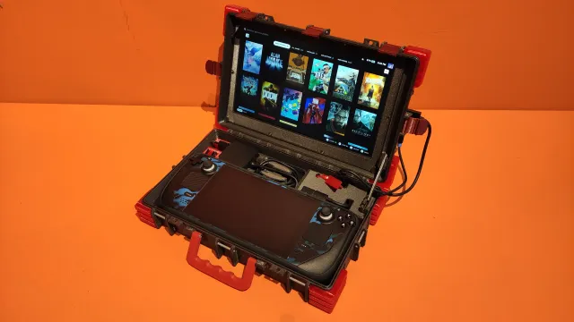
USB C water resistant connector did not arrive yet so its not on the picture.
More shells with different patterns coming soon!
The Carbon fiber infused PETG Filament with its dark olive green color I used is the following one.
TIPP:
The side button is a bit tricky, connect long enough wires to the Faketec board, slide the sledge in with the gps antenna cable already connected to the board, once the battery pack passed by the button hole you simply push the wire out and solder the button on “outside”, dont forget to slide the buttons counter nut on the cable before you pass the cable through the hole! After you connected the button to the cable slide it in and then use a thin screw driver to screw the counter nut on, its a bit tricky but totally doable ;)
Parts list:
Faketec NRF 52 DIY node ( the best and cheapest option available as of now)
gargomoma/fakeTec_pcb: A low-cost nrf52 device.
3x 18650cells source locally and connect them in parallel.
1S Lithium Ion battery protection for the in parallel connected cells:
1S Lithium Ion charger 3A:
SMA compatible antenna with region correct frequency of your own choosing or my recommendation:
Or:
Watertight USB C socket:
GPS module:
GPS antenna: HA-203
Ipex SMA adapter cable for GPS and lora module: SMA Female, 7,5CM and 5CM
Water resistant button to toggle GPS on/off:
Mosfet to power buzzer and toggle GPS on/off as NRF52 output power is to low: SI2312
Resistor to “pull down” mosfets used for buzzer and GPS so they dont draw power when not active or shut down (software shutdown)
Buzzer: (8.5x8.5.3mm 3volt)
Main power Switch:
Wiring cable: 0,5
M3 brass hot melt inserts: M3, 4,5OD 6mm:
M3 screw: 10mm
Tags
Model origin
The author marked this model as their own original creation.