Articulating Raspberry Pi Camera Mount cover with ring light

Description
PDFNB: You might want to print this with something like PETG or a higher temperature capable material. This will help to prevent warping from the heat of the LED ring.
I use an enclosure for printing, so the light levels aren't great, I have a strip of LEDs mounted to the top of the enclosure, but whatever is being printed is pretty much in shadow because of the extruder. Now with this part, I can finally see what is being printed!
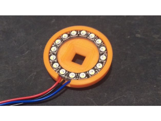
This is a modified face plate for the Articulated Raspberry Pi Camera Mount that houses a ring of LEDs, I have tested it with a ring of 16 Neopixels, available from Adafruit, and a 12 LED ZIP Circle, available from Pimoroni.
I would personally recommend getting one of the RGBW Neopixel rings, as it means you can get a nice natural white light instead of the slightly more blue light that you get when you run the RGB LEDs at full tilt to get a white colour.
You will also need a microcontroller to control the LEDs, in my case I used an ATtiny85 MCU. Depending on the power supply to your printer you may need a step down voltage regulator, pre built versions of which can be found on eBay or Amazon, or you can have a go at deriving a 5V supply yourself with a linear voltage regulator or go all fancy and build a proper switching voltage regulator like I did, details of which can be found in the 'Installation' section.
Print instructions
Category: 3D Printer Accessories Print Settings
Printer Brand: Prusa
Printer: i3 MK3
Rafts: No
Supports: Yes
Resolution: 0.15
Infill: 20%
Filament: Amazon Basics PLA Orange
Notes:
I used some supports from the build plate, the model was printed with the large circular section down on the build plate.
Post-Printing
Assembly
For installation the Neopixel ring is a nice tight fit with the part, so you should solder some wires on the back side of the ring, then press the ring into the printed part. There is a small cut out running around the ring that the wires will fit into. The ZIP Circle is a bit of a looser fit so you will need some adhesive, double sided sticky tape should be ok, superglue if that doesn't work. Again, solder some wires on first, then install the ring into the part. The wires come out of the bottom where there is a slot.
Programming
I have programmed an ATtiny85 using Arduino code that runs the LED ring.
Just use one of the example Neopixel sketches to get your program right, then flash it to the ATtiny85! I used this method here.
Installation
You can use a tiny breadboard to connect everything together, or you could use some perfboard or even the custom designed PCB that I created for this project! I had some PCBs built by JLCPCB, the details of which can be found over on Hackster. This custom board takes the 24V DC power from the Prusa i3 power supply and powers the ATtiny and the LED ring!
Finally, snap the faceplate onto the camera mount, plug all the bits and pieces in and hey presto, there is light.
Tags
Model origin
The author remixed this model. Imported from Thingiverse.

Differences of the remix compared to the original
Altered the camera faceplate to fit a LED ring light


