Lathe division mechanism (in OpenSCAD)
Description
PDFBackground
I have a very old metalworking lathe (Zyto) made in the 1930s/1940s, and it didn't have graduated dials on any axis. I made some a while ago but they weren't too great, so now I plan to make some decent ones. Unfortunately I don't have any sort of dividing equipment for cutting the graduations accurately.
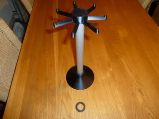
This inspired me to design this division mechanism, which is used in conjunction with the division plates I published a little while ago. The mechanism locates in the division plate's peg holes to lock the spindle - basically, it's an arm with a spring-loaded peg that fits into the holes, fixing the lathe spindle in 1 position at a time.
The dimensions of this mechanism are very lathe-specific; I am only publishing it so that others may use it as the foundation of their own designs. The STL files I have included are for my lathe; you will almost certainly have to change the OpenSCAD variables to suit your own needs, then create your own STL files.
Important : This mechanism is only suitable for very light duty - in my case, for marking dials. It is not robust enough for gear cutting or anything similar; you can try if you wish, but it's on your own head!
Creating the metal parts
The drawing shows the dimensions of the two metal parts needed to make this work - apologies for the poor quality of the drawing!
The first part is glued into the top of the arm, with the flat face towards the division plate. I used 2-part epoxy, but almost any glue suitable for metal and plastic would work.
The peg end should be rounded, to make it easier to put it into the dividing plate holes. It is also a good idea to round off or chamfer the other end of the M6 threaded rod, purely to avoid scratching the user.
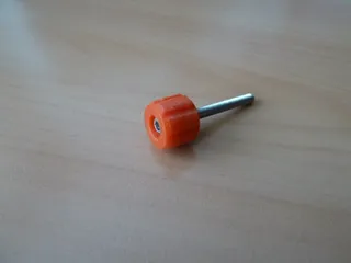
Apart from these parts, you will also need an M6 locknut, two ordinary M6 nuts, a small light spring (see pictures), and some M6 washers to complete the peg assembly. You will also need a fairly long M3 screw and nut for the bottom arm pivot.
Creating STL files from the OpenSCAD sources
The file calleddivision base.scad is used to generate both the base itself, and the arm. Each is selected by going to the end of the OpenSCAD file, commenting or uncommenting the appropriate lines (it's reasonably obvious), and then regenerating the STL files. No special libraries are required.
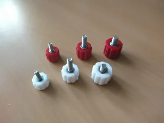
The knob can be modified in its own OpenSCAD file, but you will need one library: chamfer.scad
Print Settings
Printer Brand:
Anycubic
Printer:
Kossel Linear Plus
Rafts:
No
Supports:
No
Resolution:
Anything you like - I used 0.3
Infill:
25%
Filament: Various PLA / PLA+
Notes:
You can use any rigid material (PLA, ABS, etc.) and any settings that you like - nothing is critical.
Tags
Origine du modèle
L'auteur a marqué ce modèle comme sa propre création originale. Importé de Thingiverse.


