Tarmo5 MODS: reinforce all the frequently breaking parts

Description
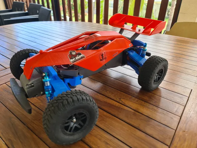
PDFTarmo5 is a great project by Engineering Nonsense. Now, my build is robust and powerful and also resistant to my son's driving skill.
→ if you are looking for my cover and wing, the page moved here : https://www.printables.com/fr/model/477310-tarmo5-cover
A 6 years old boy is very good at crash testing a car. Everytime my son crashes it, I redesign some pieces to make it stronger. After so many months of fun and broken parts, I did a lot of modifications on tarmo5 and I was requested to publish it.
If you want me to keep updating this page with new models PLEASE LIKE IT / COMMENT / post your make → it is the only way for me to know if its usefull or if it's a waste of my time
→update on 2023/06/09: FRONT IMPACT PROTECTION by reinforcement of B10 TPU part + larger front bumper (see bellow). Improved printing advices (see at the end of this page)
→ update on 2023/05/10: I got relaly good results optimizing the printing parameters for my prusa mk3s+. See a the end of this document the settings to use.
→ update on 2023/05/09: the existing tolerance between the MAIN GEAR HUB and the CV GEAR HOUSING caused some friction, partialy melting the CV GEAR HOUSING and after a while the TORQUE DUMPER broke causing a friction between the GEAR HOUSING and the upper CONTROL ARM. To avoid this, I modified the MAIN GEAR HUB, reducing the internal tolerance by 1.5%. The part is a bit stonger and the smaller tolerance reduces friction. I tried unsucessfully other mods that I finally abandonned.
I suggest you print the CV GEAR HOUSING in a visible color like red because when the torque damper will break this part may fall. Normally the color is not visible anyway.
Files to use
- MAIN GEAR HUB - C06_tolerance1.5p.stl
CV WHEEL HOUSING - CV INNER RACE - CV CAGE
At the beginning, my tarmo5 was frequently losing steel balls or breaking CV CAGE. I tried to reinforce the CV CAGE: see 3 versions on the picture : normal (blue), +4% (white) and +5%(red). I actually fusioned the original stl with a +2% and with a +5% version on prusaslicer.
The +5% version fits and seemed better at the beginning but the problem was not completely fixed.
I also reinforced CV WHEEL HOUSING enlarging the external part even if there was no visible problem. → abandonned on 23/05/10 see bellow
After a post in reddit and many very nice answers, I finally found the solution :
The tolerances of this project are globally too high for my printer. Thanks to u/cobblepots99 I could verify that it is well calibrated. After many tries I ended up printing the 3 parts in contact with the steel ball as follow:
- wheel housing fusioned with a XY -1.5% scaled copy of itself
- CV cage fusioned with a XY 1.5% scaled copy of - itself
- CV inner race fusioned with a XY 1.5% scaled copy of - itself
Those parts are available here.
NOTE: my CV WHEEL HOUSING - C01_ corrected_reinforced_reduced_1.5p.3mf
edit on 23/05/10: I removed the external reinforcement because it's not necessary and in some cases it can cause friction.
is modified as follow:
- "corrected" : the hexagonal part in contact with the wheel was too small, I increased the size so it fits perfectly with my wheels (the recommended model).
- “reinforced” : the external part is a bit larger to make it stronger → abandonned
- "reduced" : fusioned with a XY -1.5% scaled copy of the botom part of itself (the part in contact with the balls)
previous version renamed : old_CV WHEEL HOUSING - C01_ corrigé_renforcé_réduit_1.5p.3mf
new version : CV WHEEL HOUSING - C01 - corrected_reducedLT.3mf
After mounting the 3 parts with the balls, If it is a bit too tight, I suggest you decrease to 1% in priority the scaling of the CV CAGE as the 2 other parts are important to hold the stell balls in place in max extension position (when shocks are fully extended).
I tried using silicon grease but now I prefer dry PTFE lube.
CV GEAR HOUSING
The same 1.5% modif was applied to CV GEAR HOUSING - C02 ajusté 1.5p.3mf
SHOCKS improvements :
My shocks were not hard enough for the weight of my car.
It came with 4 springs per shock (2 longs & 2 shorts). The idea was to use either ones or others but I combined 3 of them and I designed a piece to connect the springs.
Raccord ressorts v1.3mf
Now it is perfect.
Those shocks are cheap but really good and you can adjust it to fine tune.
https://fr.aliexpress.com/item/1005003230553475.html?spm=a2g0o.order_list.order_list_main.64.4f3e5e5bfwPVnv&gatewayAdapt=glo2fra
Please note that the springs do not have the same elasticity. First make a test to identify the harder ones. Check on my picture to see where is the softer one.
EDIT on 23/05/10 if you use the last version of the enclosed gearbox by flyntm, you should order 1cm longer shocks for the rear.
The wheels direction is not enough firmly maintained
So I redesigned following pieces. After many tries I found the right percentage of modification for those parts :
- Steering Link - A10 - tolerances 104p.3mf 104%
- FRONT BEARING HUB - A05 - tolerance 86p.stl 86%
- FRONT BEARING HUB - A06 - tolerance 86p.3mf 86%
- END CHASSIS - B04 - tolerance 92p.stl 92%
EDIT on 23/05/10: now I replaced the steering link with a metalic adjustable one.
HEAD ON COLLISION / FRONT IMPACT
Head on collision (front impact) is absorbed either:
- by the bumper: use Bumper - B07-T-largeLT here
- by the front wheels. In this case the shock is supposed to be absorbed by the TPU B10 part that will break after a while.
1. Front bumper:
This bumper is designed for a better absorption of front shocks and also reduce the impact on the front wheels. Available here: https://www.printables.com/fr/model/501561-tarmo5-larger-front-bumber-normal-and-fpv-version
2. Reinforced B10 TPU part
Strong or repeated collision in the front wheels will damage the ARMS and B10 screw holes. The larger bumper will reduce those shocks but will not eliminate them. The arms are attached to B10 that is printed in TPU to absorb a part of the impact force but after a while the screw holes attaching the arms will be damaged (see a picture).
I modified B10 part as follow: reduced the size of the holes to fit the M4 screw size. Removed the space to incrust the screw head into the part. I use a longer M4 screw with a washer.
→ FRONT A PLATE - B10-T-reinforcedLT.stl
→ see picture
PRINTING PARAMETERS TO GET STRONGER PRINTS:
To get stonger prints, I replaced PLA with eSUN PLA+.
For the slicer settings, here is the theory. Each of those settings is explained in details by different videos of CNC KITCHEN so if you are interested please watch those videos that will explain everything much better that I do.
- printing temperature 215°. I used to print at 200° C because that was the best printing temperature to get perfect print towers. But higher temperature combined with the following settings increase the adherence between layers resulting in stronger parts without losing significant details. The basic idea is that you have to choose between nice aspect of strong part. The best appearance will be with 25% overlap and 195°C (depending on your filament brand). The most resistant part will be with 40% overlap and 215°C but it will case some artefact on surface due to overextrusion, some stringing… so it may require a bit of post printing treatment.
- reduced printing layers: 0.15 or better 0.10 with a 0.4 nozzle. And 0.2 with a 0.6 nozzle. I used to use “0.2 quality” settings with a 0.4 nozzle and 0.3 with a 0.6 nozzle. But combined with the other settings, a thiner layer helps to compress the plastic to get a better adherence between layers and a higher density of the final result, so a stonger print.
- For the last parameter I first applied the idea of CNC kitchen (point1) but finally I realized that point 2 is better. The ovelap + high temp results in good adhesion between melted layers of filament:
- Extrusion width. In Prusa slicer, it is the first parameter in “print settings”/advanced. Larger extrusion will allow a better adherence betwing 2 lines in the same layer. I increase most of the parameters here by 150% (except 1st and last layer and supports).
This has a direct incidence on the “perimeters” setting. 200% extrusion width 1 perimeter = 100% extrusion width with 2 perimeters, but the first is much stronger. So adjust this parameter with the perimeter setting. Basicaly extrusion width = x 150% and I reduce a bit the perimeters. - But after many testing, I finally keep default settings for Extrusion width and increase the following setting : print settings/Advanced/Overlap/Infill-perimeters overlap. I set it to 40% if there is no support. If there are supports I have to reduce the temperature and overlap.
- Extrusion width. In Prusa slicer, it is the first parameter in “print settings”/advanced. Larger extrusion will allow a better adherence betwing 2 lines in the same layer. I increase most of the parameters here by 150% (except 1st and last layer and supports).
→ I don't pretend to be an expert in printing materials. As I was asked to I just share my own conclusions after lots of testing. If you want to share your own experience and your knowledge, please send me a message. I will continue sharing my recipies here.
The parts I print with those settings have a higher weight for the same volume, the print density is higher and the resistance also. Tested with PLA+ but I will use the same logic with TPU to get stronger TORQUE DAMPER.
Tags
Origine du modèle
L'auteur a remixé ce modèle.