Expanding rotating table


Description
PDFIntroduction
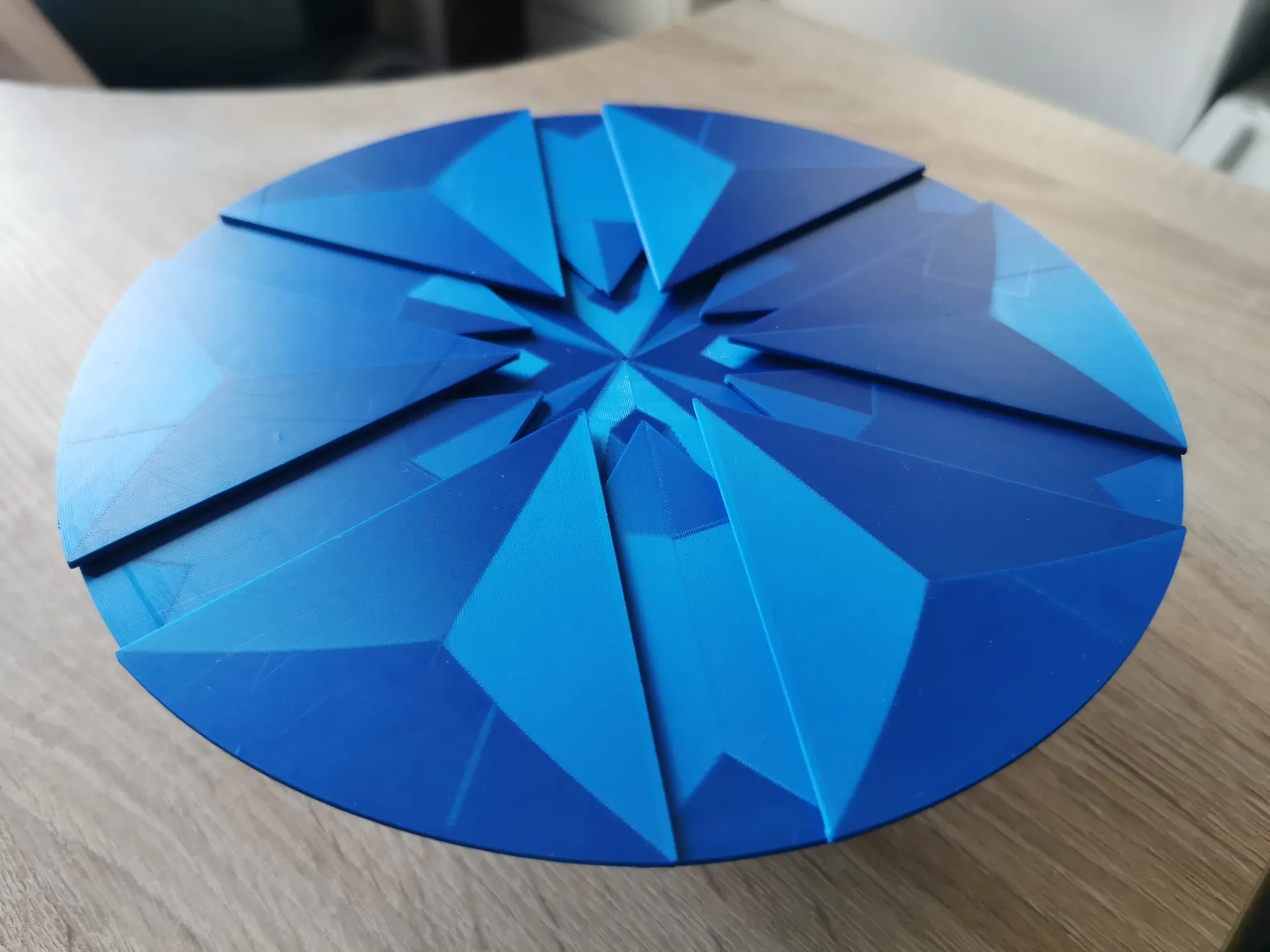
The circular expanding table idea is very old for example the “Jupe table” patents are from the beginning of 19. century. But I have not seen a 3Dprinted working scale model of it so I made one :).
The idea has been in my head for sometime but has always seemed too daunting of a project (it is), now thanks to the competition I decided to finally give it a try.
My inspiration for the final (third) mechanical solution is mostly from 2 YouTube videos.
https://youtu.be/uVbo7ycpkeI - “Making the Fletcher Capstan Table” this provided mostly the inspiration to actually build something like this, and was also one of the first videos I have seen about these types of tables that I stumbled upon while looking for some expanding mechanisms for an other project.
https://youtu.be/26ACDeOPllk - “Table Kit: Trial, Error & Lessons Learned” very useful discussion about how to design these kinds of tables (or other mechanical gadgetry)
State of project
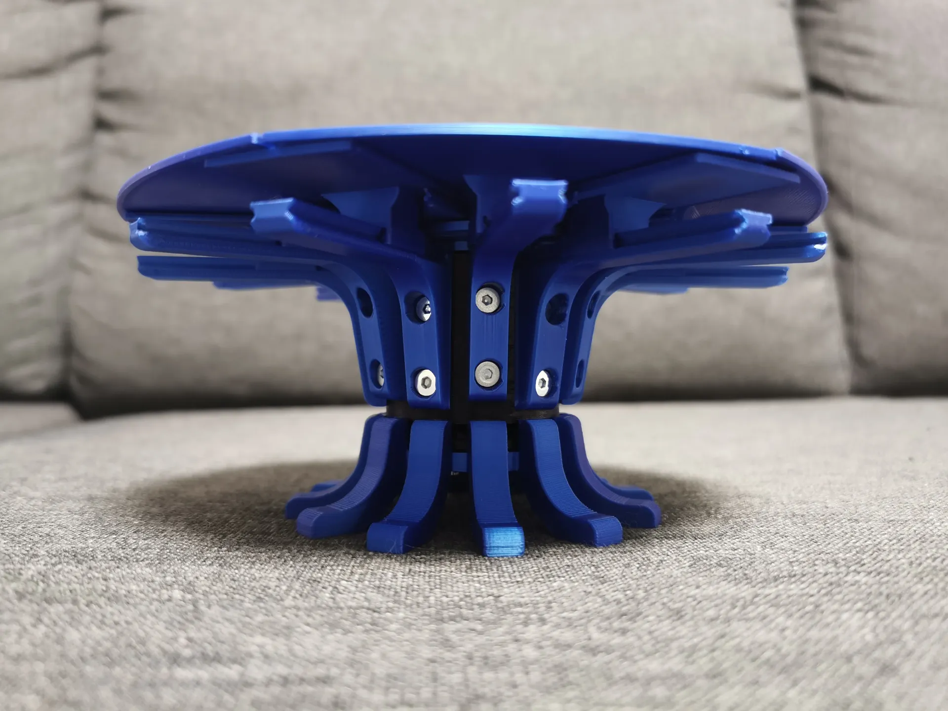
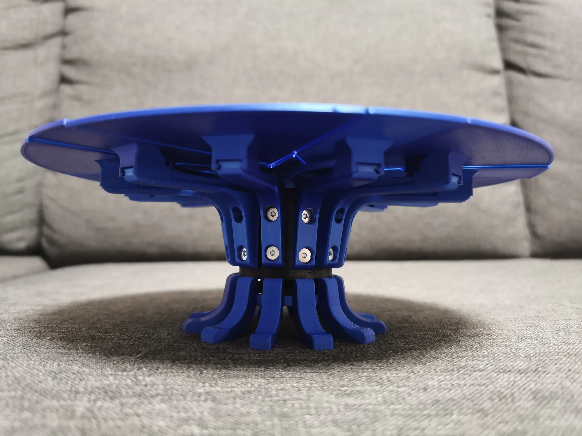
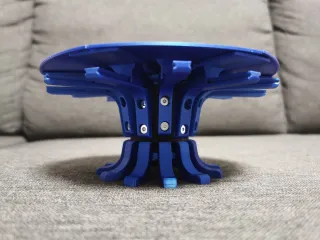
The files that are included work and get you to the result seen on pictures and video. But I have some ideas to improve on the table. For example a ring around the table that would make the compact tabletop true round and hide the cap between the table top and guide arms.
So it is ready to go and also a WIP…
I will add a log of changes hear if there is anything new ;)
21.05 - Assembly guide finished and images fixed
Design considerations
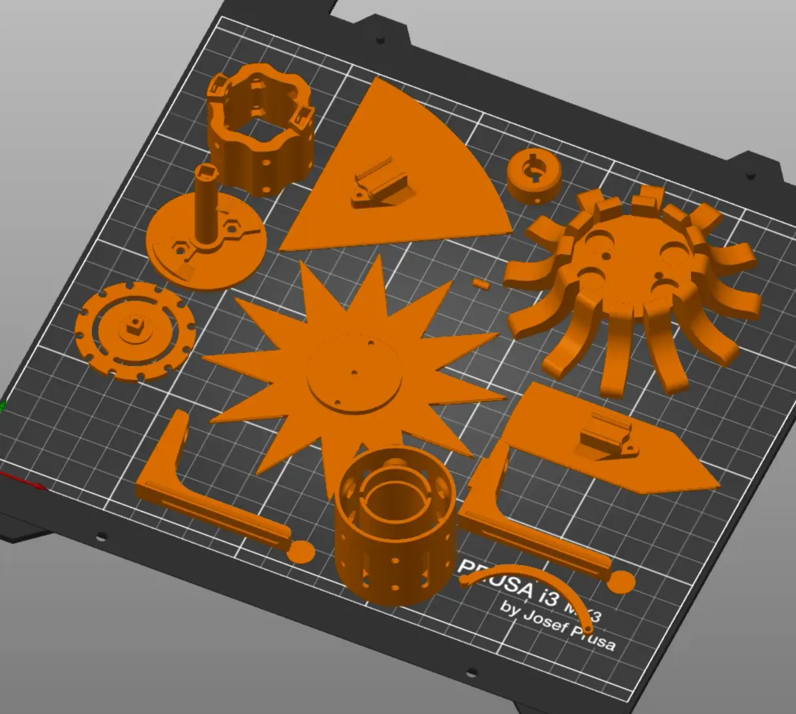
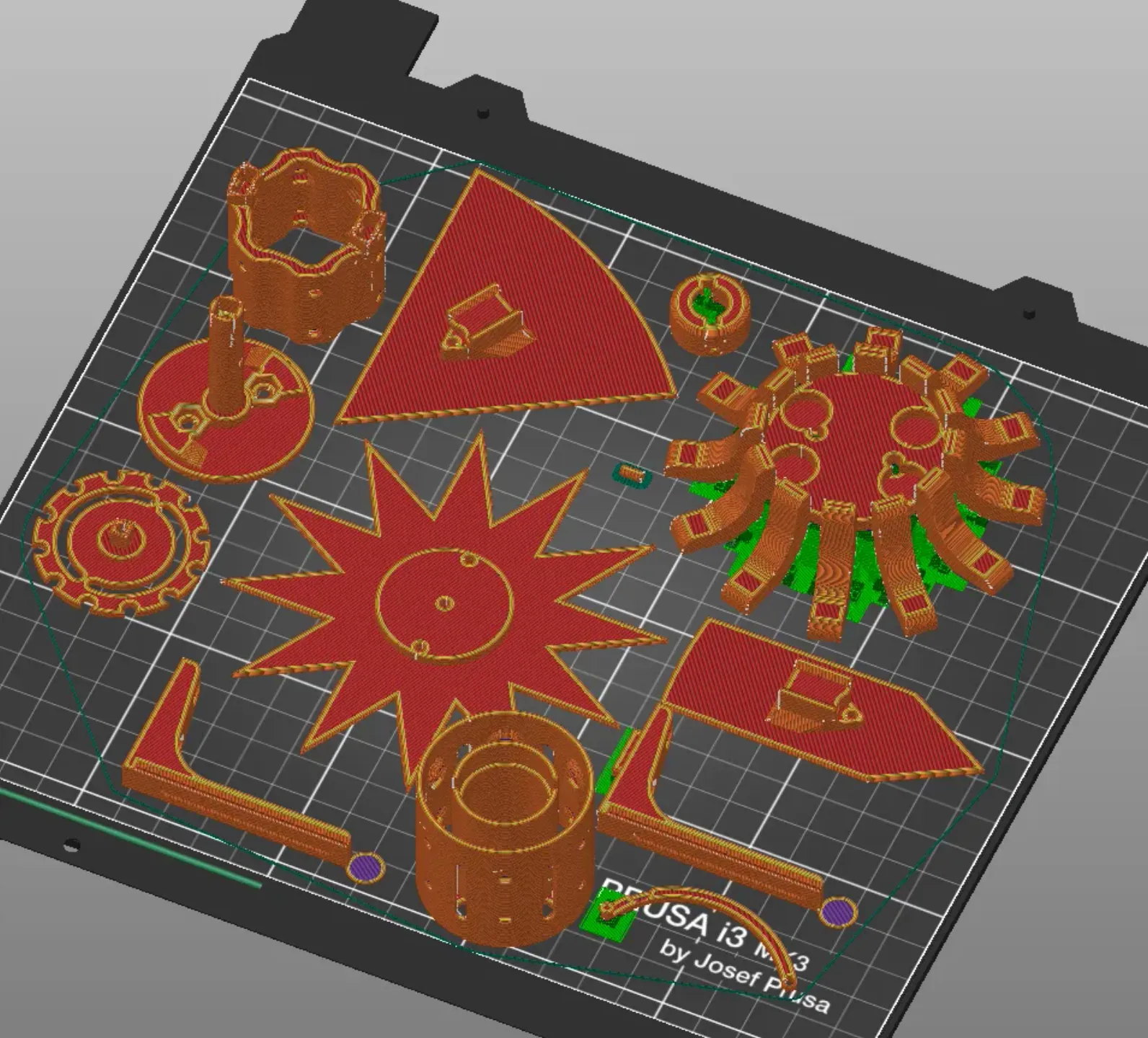
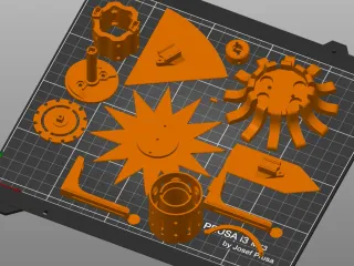
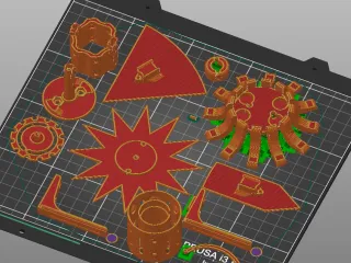
Print settings
While at fist I had ideas about using a small nozzle and making detailed intricate mechanics I ended up using the standard 0.4 mm nozzle, 0.2 mm layer height and mostly standard PrusaSlicer settings for all parts. There was 2 reasons for it. Firstly I had only 10 evenings of time when I finally gave up on version 2 of the design and started with a clean sheet, so there was limited time to thinker with tolerances (and strength). Secondly using standard settings and material (Prusament) means that anyone interested could also print one and hopefully get the same results.
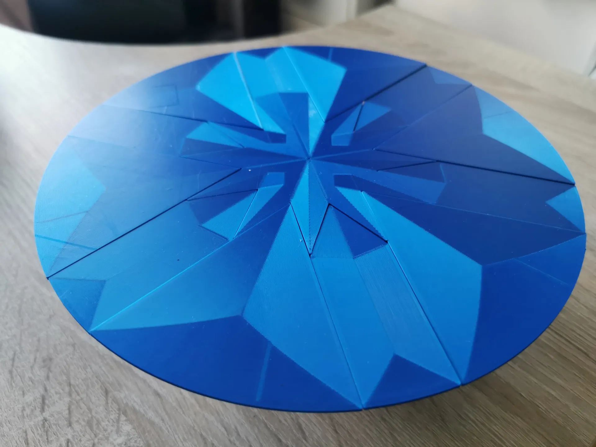
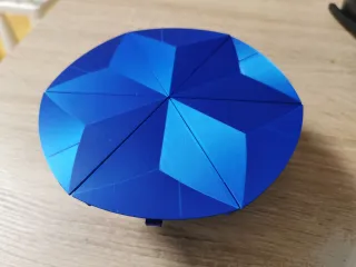
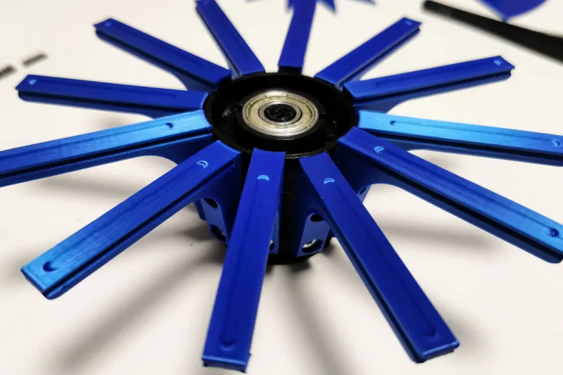
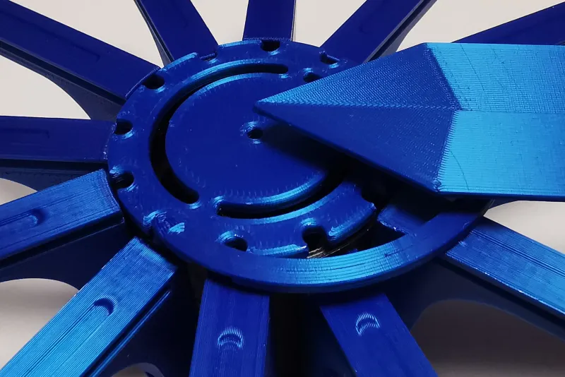
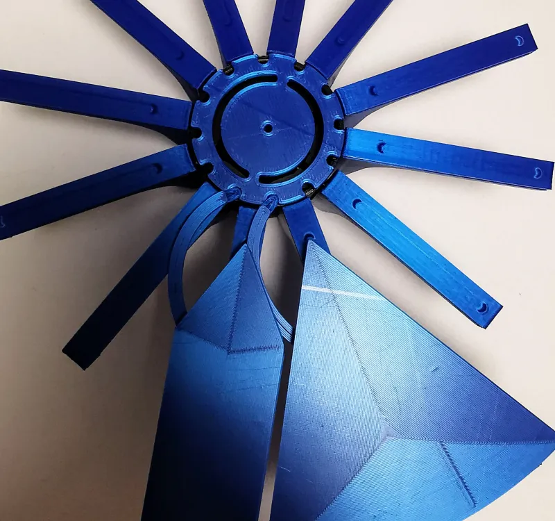
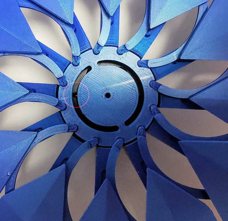
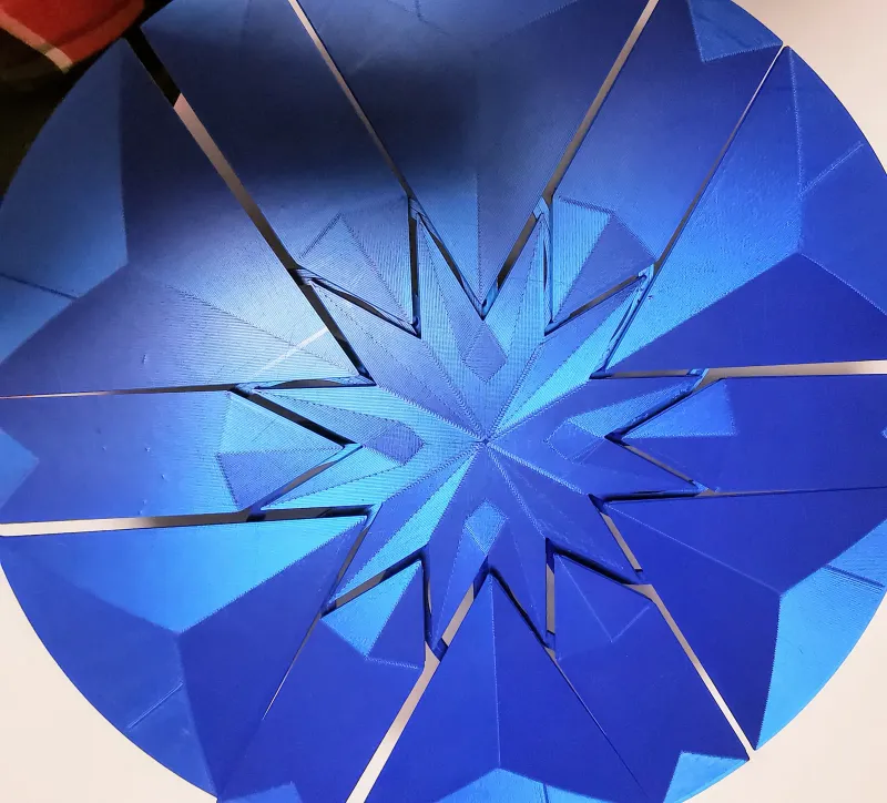
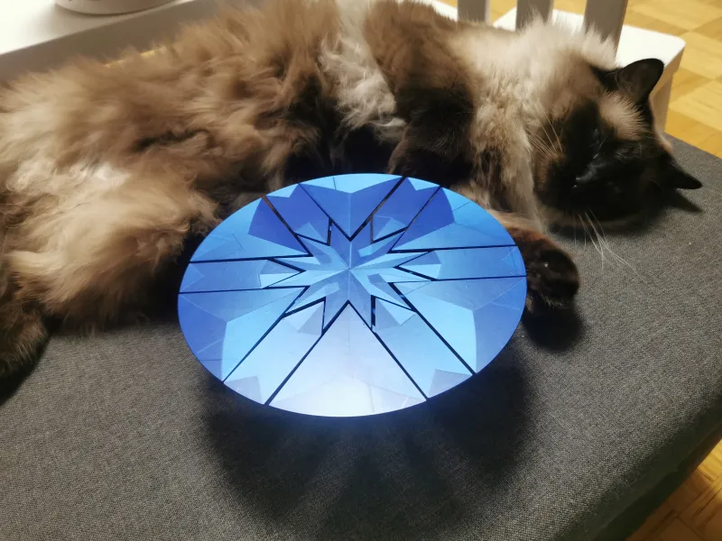
As the expanding movement of these types of tables is so mesmerizing I wanted to add to it by printing in a shine/silk filament and using special infill patterns on the table top leaves.
Ended up going with lovely Prusament PLA Royal Blue and concentric pattern. Some parts are printed in black to hide them a bit.
All the print settings used for the parts are included with the “Rotary table with settings(BOM)” 3mf files, the BOM version just has the right number of objects to complete the build
Fits
Another point that helped me and will help others is that the fits used in the design are relatively loose. The only exception of that is the slide for the table leaves that needs to be loose enough that the leaves slide but not too much wiggle room so the leaves would all be on one plane.
Hardware
There was no goal to keep hardware to a minimal but I tried to use hardware that is at least common, some parallel pins, screws, nuts, bearings, all in standard sizes
This table mostly works in our puny little regular gravity but some extra artificial gravity (a.k.a. magnets) helps things move in a more repeatable manner.
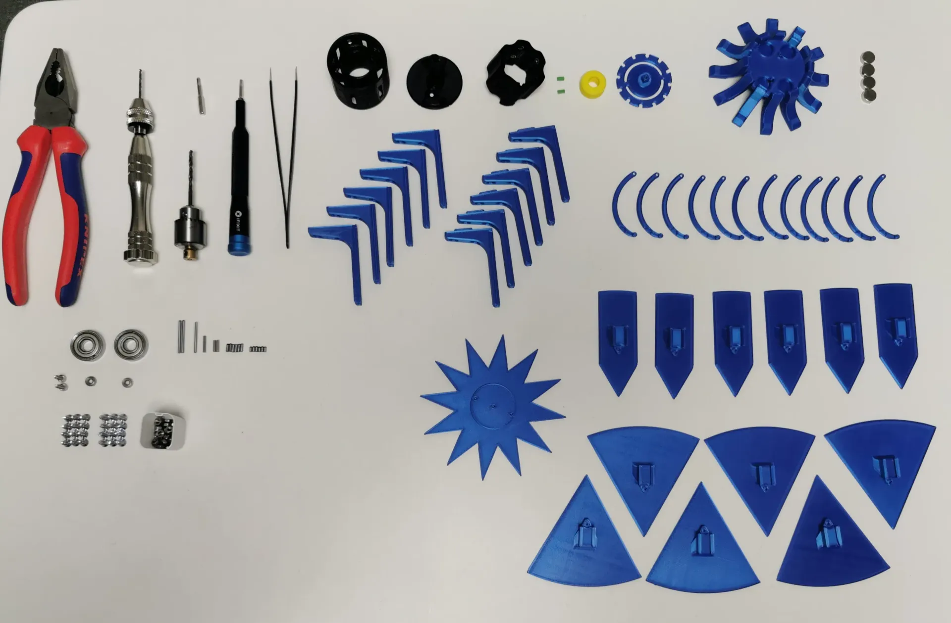
The Build Guide
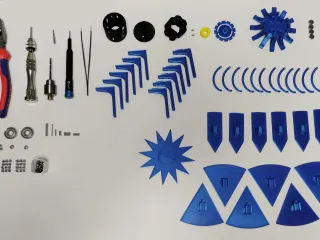
BOM
| No | Name | Quantity | Print/buy | Notes |
|---|---|---|---|---|
| 1 | Lower stator | 1 | ||
| 2 | Drum | 1 | Supports advisable for bearing seat | |
| 3 | Pin 3x6 | 2 | Print or Buy | Print or DIN 6325 or similar |
| 4 | Dart lifter | 1 | ||
| 5 | Star lifter | 1 | Needs support probably | |
| 6 | Upper stator | 1 | ||
| 7 | Dart guide | 6 | Needs support | |
| 8 | Pie guide | 6 | ||
| 9 | DartWbase | 6 | Concentric bottom infill | |
| 10 | PieWbase | 6 | Concentric bottom infill | |
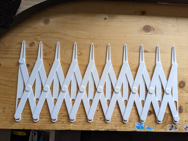
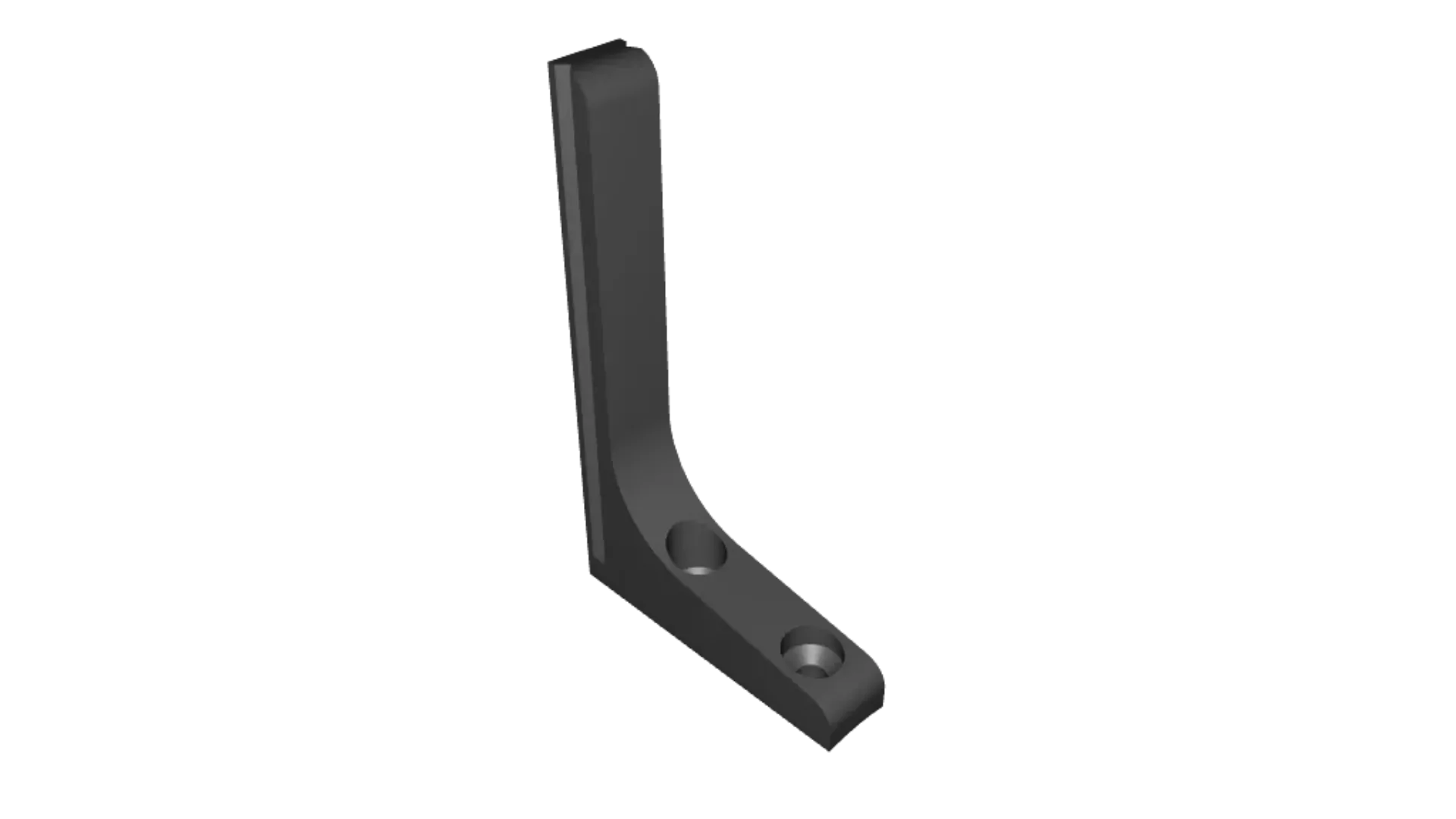
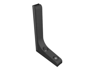
| 11 | Spiral arm | 12 | Needs support | |
| 12 | Star | 1 | Concentric bottom infill | |
| 13 | Feet | 1 | Needs support | |
| 14 | Main bearing | 2 | Buy | 608 8x22x7 “rollerblade” bearing |
| 15 | Dart lifter bearing | 2 | Buy | 683 3x7x3 bearing |
| 16 | M3 hexagon nut | 26 | Buy | DIN 934 or similar |
| 17 | M3x8 screw | 12 | Buy | DIN 7991 or similar Countersunk Head |
| 18 | M3x12 screw | 12 | Buy | DIN 7991 or similar Countersunk Head |
| 19 | M3x8 screw | 2 | Buy | DIN 912 or similar |
| 20 | Pin 2x24 | 2 | Buy | DIN 6325 or similar |
| 21 | Pin 2x22 | 1 | Buy | DIN 6325 or similar can be a bit shorter |
| 22 | Pin 2x12 | 1 | Buy | DIN 6325 or similar |
| 23 | Pin 2x8 | 2 | Buy | DIN 6325 or similar |
| 24 | Pin 2x6 | 6 | Buy | DIN 6325 or similar |
| 25 | Pin 2x4 | 6 | Buy | DIN 6325 or similar |
| 26 | Magnet 10x4 | 4 | Buy | Disc magnet for gravity enhancement |
Step by step guide
This next part has been mostly added on 20.-21.05
Some general pointers
If a nut does not want to stay where ii should add a tab of glue on one flat of the nut, any glue would probably work, would suggest gel type cyanoacrylate glue or plane old goopy PVA, it just needs to hold the nut in till you have secured it with a screw.
If you need to pull in nuts, it is advisable to first clean up the screw hole with a drill bit but don’t use power tools to drive the drill bit as it is easy to make the holes too big. I mostly use a small drill chuck I hold by hand for these kinds of tasks.
Before assembling remove supports and the “mouse ears” from parts.

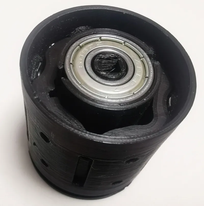
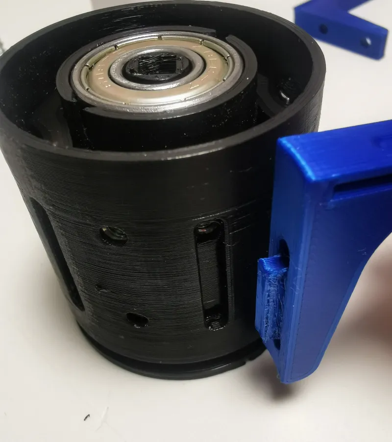
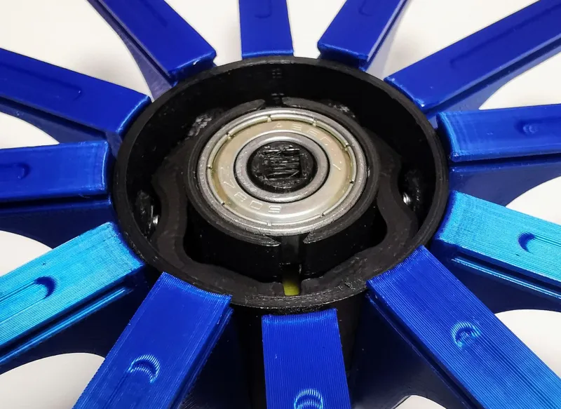
Mating the bearing surface to the bearing
Prepare
1 Drum (No.2)
1 Main bearing (No.14)
For everything to align up in the end the bottom of the Drum (should have called it a barrel 😊) must match up whit the bottom of the bearing. It is highly likely that you will need to trim the bearing seat down. Even if you print with supports there might still be some amount of sag due to the geometry, I didn’t use supports there and just used the tip of a knife blade to cut some of the sagging material out. (You could use supports there to minimize the trimming). Remove material until you can run a ruler or other straight edge over the bottom of the Drum without it catching on the bearing.
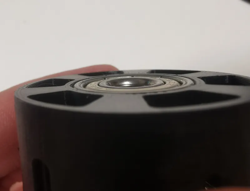
Remove the bearing once the fit is good
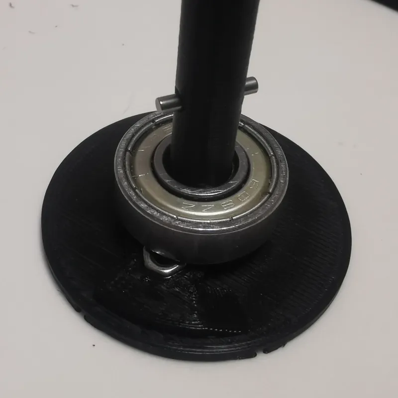
Assembly of the base
Prepare
1 Main bearing (No.14) (from last step)
1 Lower stator (No.1)
2 M3 nuts (No.16)
1 Pin 2x12 (No.22)
Add Nuts in the lower stator. If needed pull them in with the help of a bolt (if they want to fall out add a bit of glue). Next push the main bearing on to the lower stator shaft. Make sure it reaches the bottom of the shaft. Push 2x12 pin through the shaft so it is equally sticking out on both sides. It should go in with a bit of force but if you feel that the shaft could break you can make the hole bigger with a 2 mm drill bit (it is not a big issue if the pin is in there loosely if it remains perpendicular to the shaft, only bit more annoying to assemble).
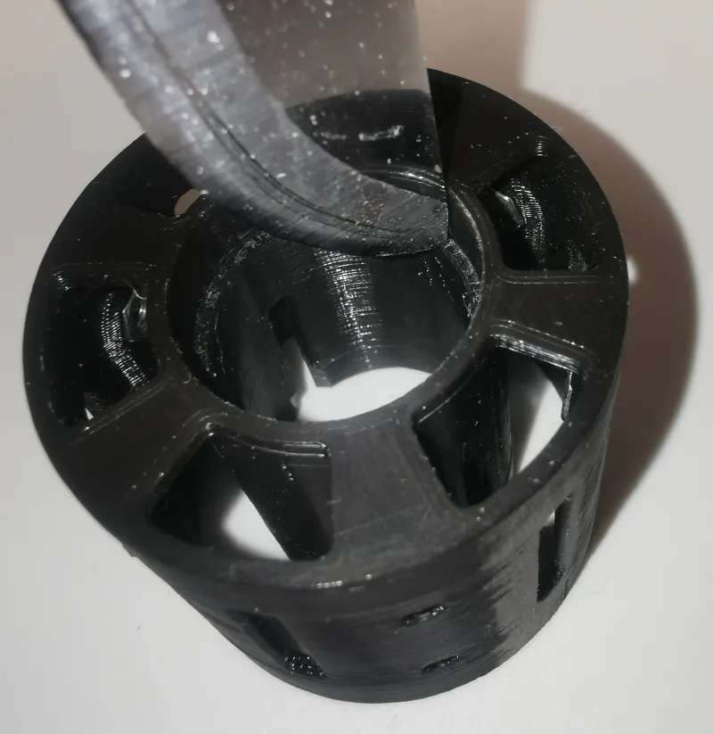
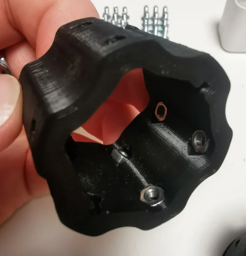
Drum assembly
Prepare
1 Drum (No.2) (from previous step)
12 M3 nuts (No.16)
Add the nuts to the cutouts from the inside… this is a bit tedious, I used tweezers to but the nut in the approximate location and then used a longer screw to pull the nut in. if the screw is too tight in the hole you can use a 3 mm drill bit to make the hole a bit larger.
For some reason (some slicer + printer combination maybe) I had always 2 nuts that wanted to fall out. If you have a similar issue, you can add a bit of glue or just leave a screw in there holding the nut till later.
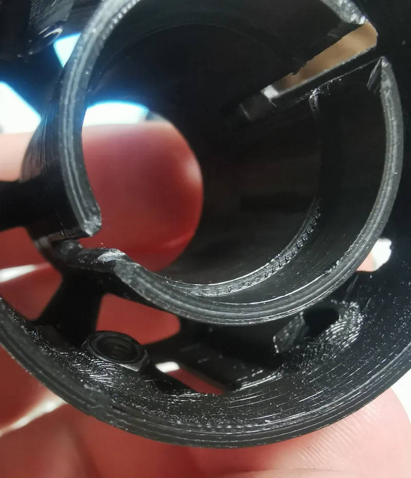
Now add the Drum over the bottom main bearing to finish up.
Dart lifter assembly
Prepare
1 Dart lifter (No.4)
2 3x6 Pin (No.3)
2 Dart lifter bearing (No.15)
12 M3 nuts (No.16)
Take a 3 mm drill bit and clean all the holes in the star lifter part. I strongly advise to do it by hand.
Now add the bearings in the dart lifter and secure them with the pin. I personally like the printed pin more in this position as the proper pin has a tight fit on the bearing (but the bearing might be too loose on the printed pin and loose some accuracy.
Now add all the nuts to the hexagonal cut outs same as the previous step. Carefully align the cutouts in the dart lifter to the cutouts in the drum and drop it in there.
Star lifter assembly
Prepare
1 Star lifter (No.5)
2 Pin 2x8 (No.23)
1 Main bearing (No.14)
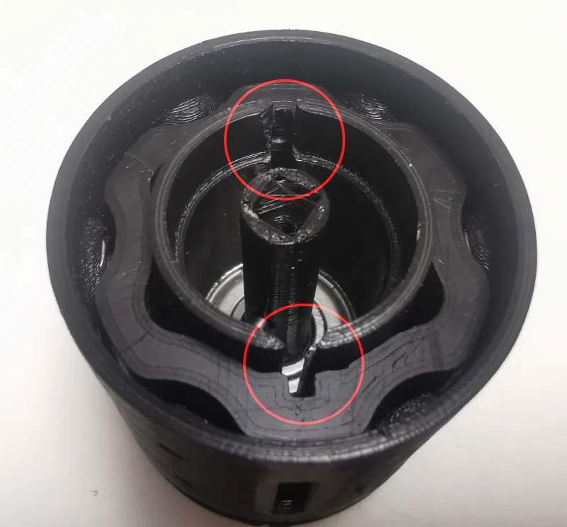
Insert the pins inside the Star lifter, first push them in so they poke out from the center, then pull back so the end of the pin is flush with the plastic part.
Make sure pin in the lower stator is aligned with the slot in the drum and drop the star lifter in over the lower stator shaft, push it in as deep as it goes.
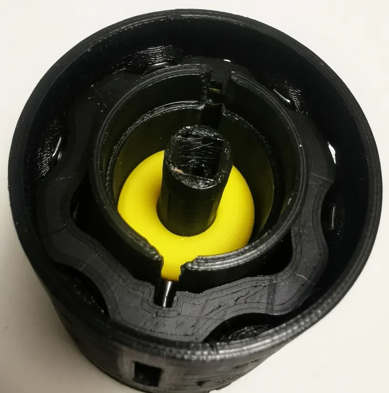
Now test that when you rotate the drum in relation to the lower stator that both the lifters move up in the same region of rotation (star lifter moves more and for longer). When everything moves correctly add the second Main bearing (608)
Adding the guides
Prepare
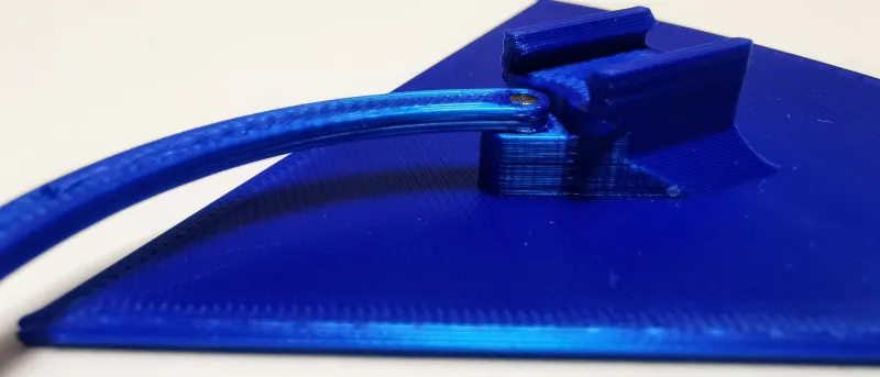
6 Dart guide (No.7)
6 Pie guide (No.6)
12 M3x8 screw (No.17)
12 M3x12 screw (No.18)
Screw in the Pie guides (these are the stationary ones) with 8mm screws and Dart guides the ones with the tab on the end with 12mm screws. Screw the parts together with light force. Make sure dart lifter and dart guides are free to move up and down in the drum, if needed loosen the associated screw ¼ turn or trim away the tab sides on the guide.
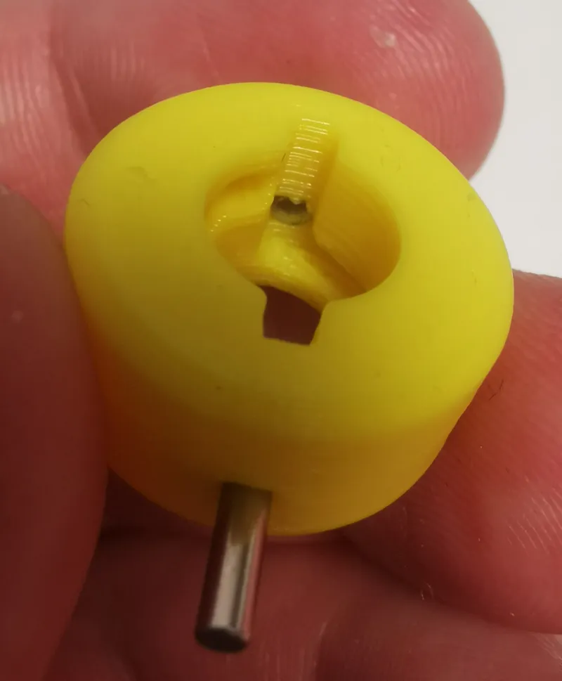
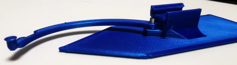
Dart subassembly
Prepare
6 DartWbase (No.9)
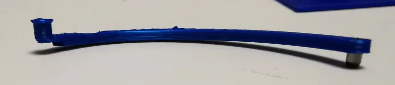
6 Spiral arm (No.11)
6 Pin 2x6 (No.24)
Push the pin through the spiral arm from the side with a printed “pin” (conical side first) so that the spiral arm is roughly in the middle of the pin. Then push the pin in the hole in the bottom of DartWbase part.
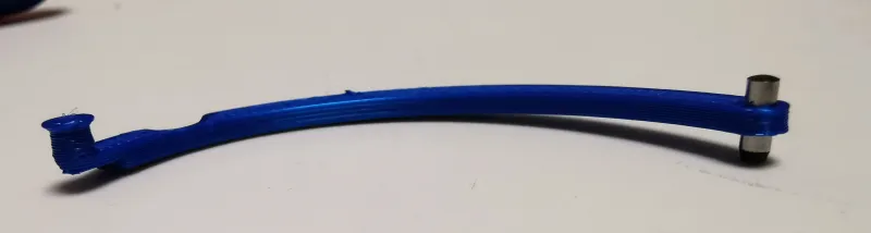
Pie subassembly
Prepare
6 PieWbase (No.10)
6 Spiral arm (No.11)
6 Pin 2x4 (No.25)
Push the pin through the spiral arm from the side with a printed “pin” (conical side first) all the way so the not conical side is flush with the surface of the spiral arm. Then push the pin in the hole in the bottom of PieWbase part.
Star sub assembly
Prepare
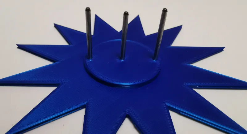
1 Star (No.12)
2 Pin 2x24 (No.20)
1 pin 2x22 (No.21)
Insert the longer pins in the outer holes and the shorter pin in the center. Try to get them as straight as possible, it is a bit finicky.
Tabletop assembly
Prepare
1 Upper stator
And all the subassemblies from previous steps.
Start by matching dart guides to dart sub assemblies and pie guides to pie subassemblies, not all parts print the same so there might be sets that don't fit together and some that are too loose. the movement should be smooth and easy but not wobbly. If needed go over the slots in the Pie/Dart assemblies with a knife lightly.
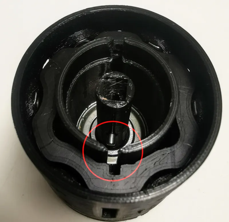
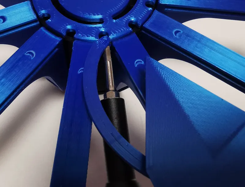
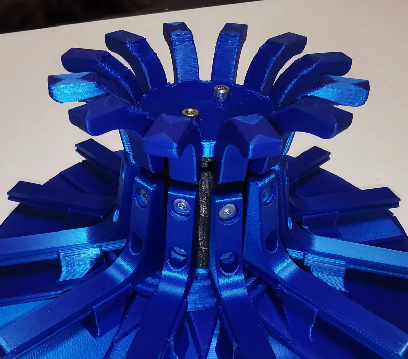
next step is installing the upper stator into the lower stator. First align the parts as shown on the picture. When the bearing is in the shown position the small slot in the dart lifter must coincide with the start of the slot in the upper stator.
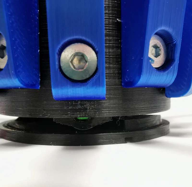
Now, position the drum so that the dart guides are lifted and cannot be turned forward, now turn back 1,5 positions so the openings in the upper stator are between the guides.
Insert the first dart subassembly on to the dart guide and connect the printed pin of the spiral arm to the upper stator. I used the end of a hex key to push it in from the side. Now make sure that if you turn the drum all the way back that the tip of the dart reaches the center of the table.
If everything is ok turn the drum back to the position described before and add the first Pie subassembly and keep adding the Dart and Pie subassemblies till they are all added.
Check that the parts move as expected and are relatively aligned. You will probably need to pull the darts down manually (we will fix it in the next steps).
If the angles of the tabletop leaves seem off, they can be adjusted by tightening/loosening the screws holding the guides a little bit.
If everything is ok, add the Star subassembly the long pins need to drop in the small cutout in the dart lifter.
From my experience the parts need a bit of working in to move as smoothly as in the examples. The leaves tend to get caught on each other at first.
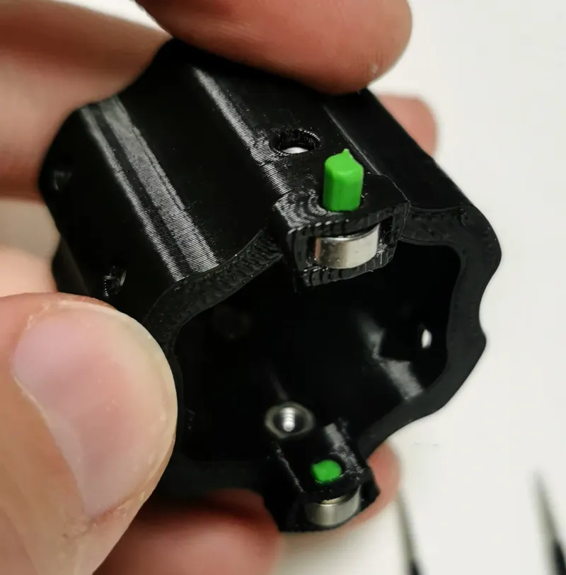
Adding the feet
Prepare
1 Feet (No.13)
4 Magnets (No.26)
2 M3x8 screw (DIN912) (No.19)
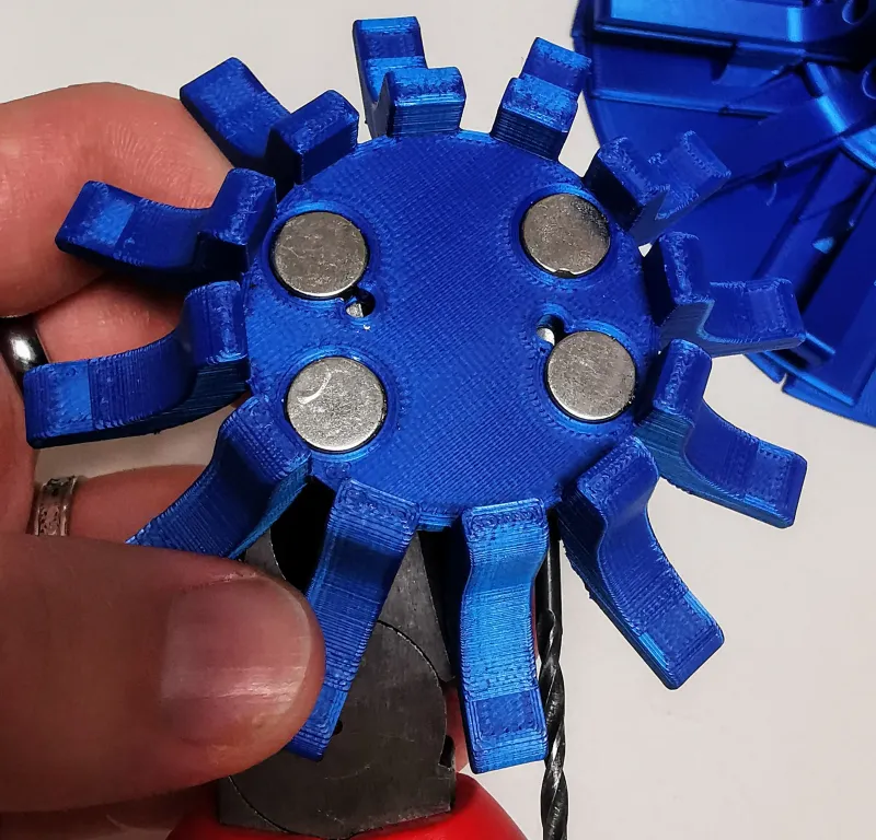
Turn the drum so the table is in its small position and put it upside down.
Add the magnets to the cut outs of the Feet, it is easier if you add something magnetic on the other side of the parts otherwise the magnets can pop out and potentially hit or pinch you. Add the table so the magnets are hidden between the lower stator and legs (there are cutouts in the bottom of the stator to fit over the magnets), secure the two parts with 2 M3 screws.
Congratulations, you now have one cool table 😊 the cat approves ;)
Final note on the license
At the moment I have prohibited remixes but I think I will allow them when I have really finished with the design ;)
Tags
Model origin
The author hasn't provided the model origin yet.