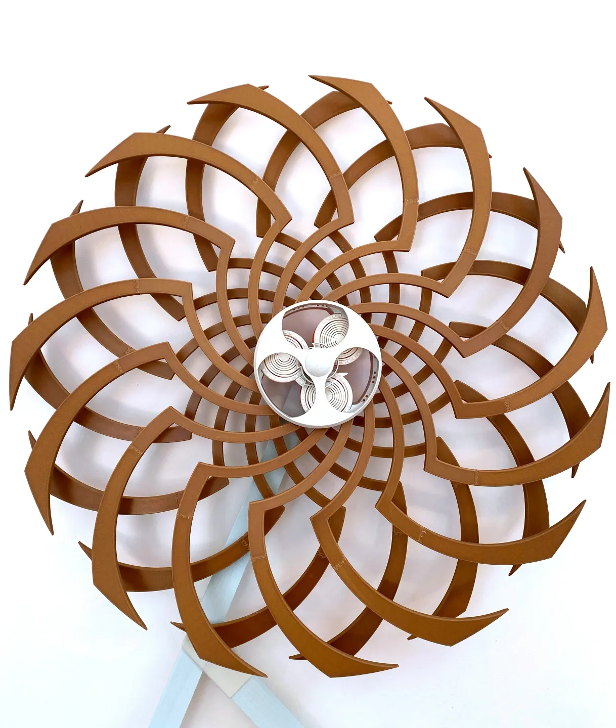
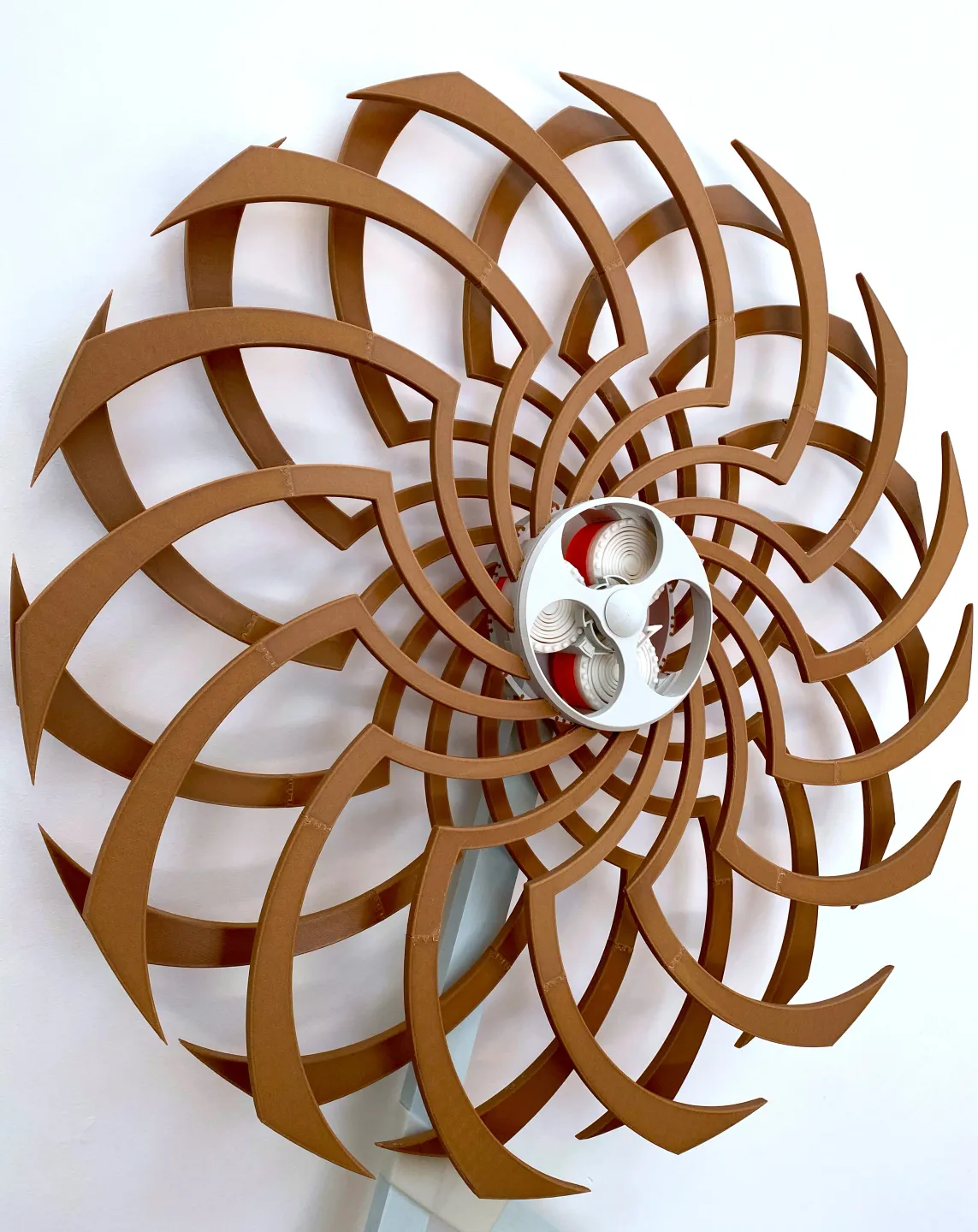
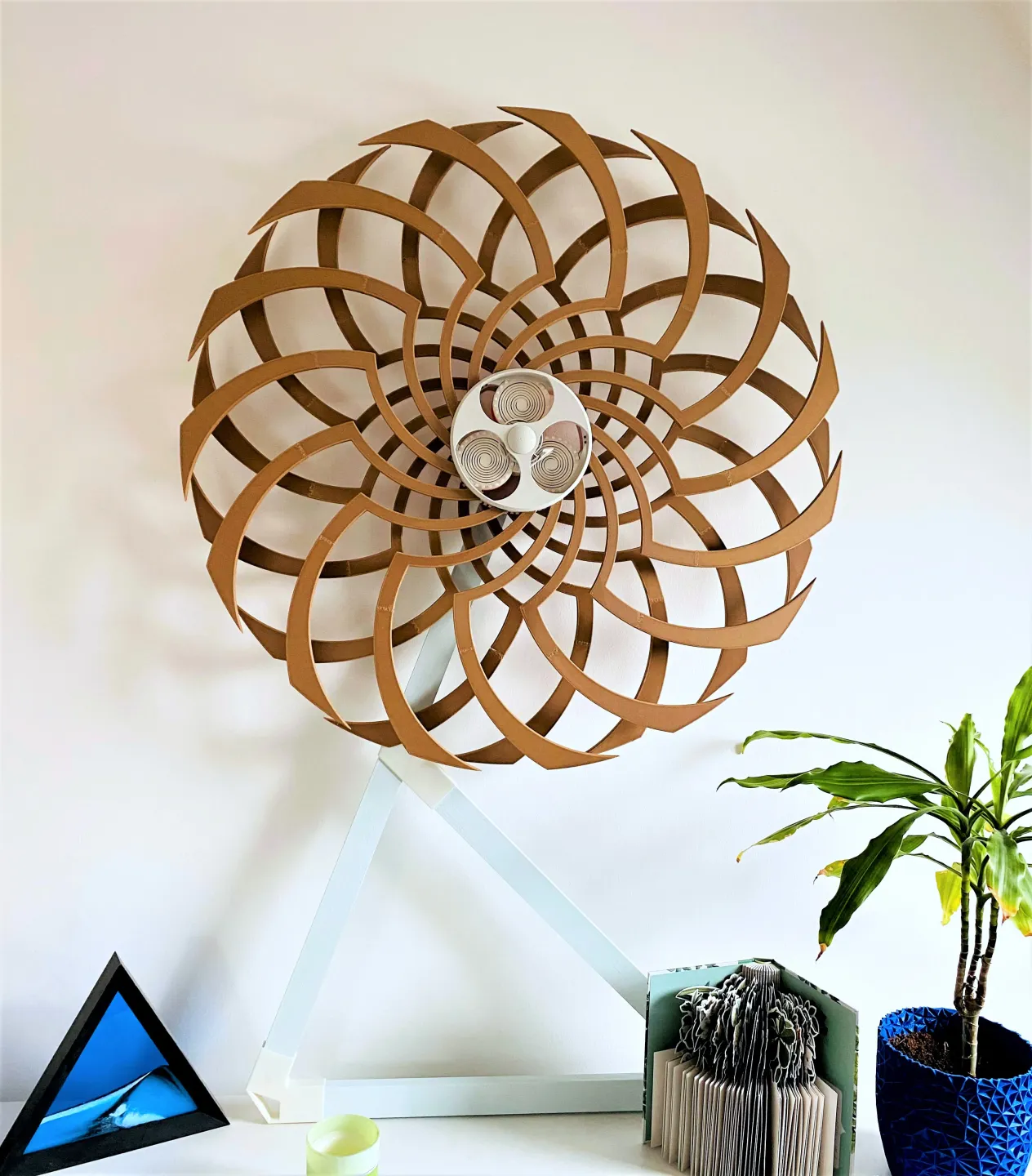
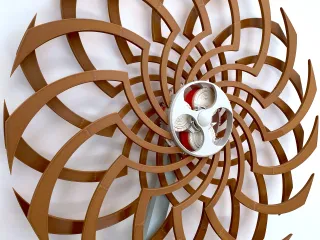
KiMe - fully 3d printable kinetic sculpture

Beschreibung
PDF01. Introduction
This project started two years ago with the intention to surprise my girlfriend for her birthday. She really enjoys those sculptures and since I enjoy 3d printing, I thought that would be a perfect match. After way too many iterations and many failures, I'm happy to share the final design with everyone who also loves mechanically moving objects.
Before we jump in: This model was heavily inspired by the work of David C. Roy (credit to him at this point) and was set out to be as fully 3d printable as possible. After several trials it became clear that printing the shaft as well as the bearings for the moving parts in PLA wasn't gone work due to low stiffness and too much induced friction. For this reason, I couldn't replace the metal shaft as well as the ball bearings with 3d printed substitutes just yet. That being said, this design does not require external rotary metal springs to store energy nor neodymium magnets to release it in the right way again. The complete mechanism is 3d printable which differs from existing designs and in turn makes the whole build more accessible.
Numbers:
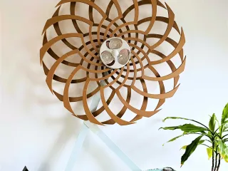
- Size: ~830x830x100mm (height x width x depth)
- Part count: 93
- Printing time: ~135h (on a single Prusa Mini with default profile 0.2mm SPEED)
- Runtime: 8-12min (depending on intensity of spin-up & bearings)
- Weight: ~2kg (1.35-1.5kg for the wings alone)
- Eyecatcher: 10/10
Video:
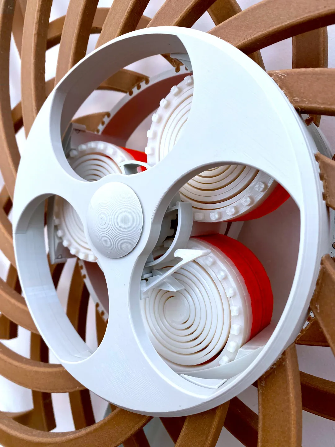
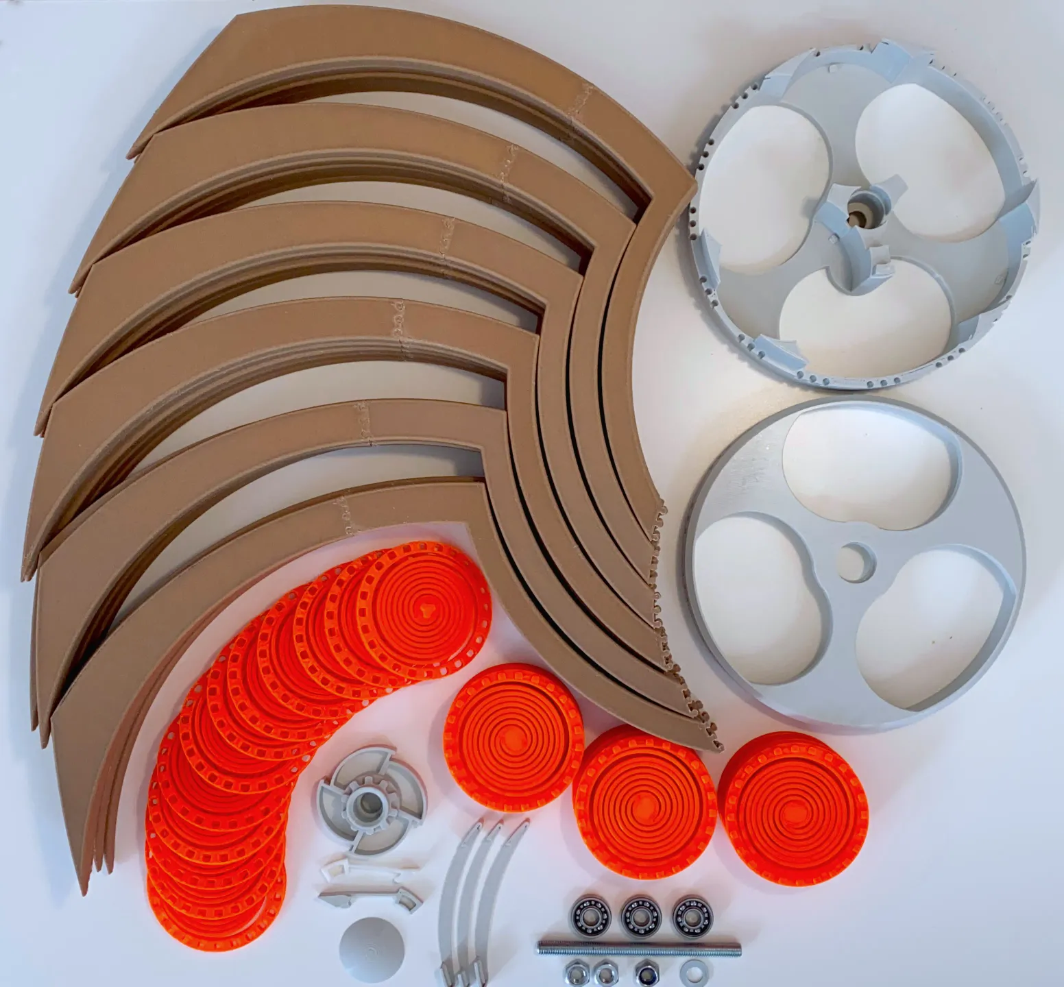
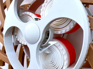
02. Parts & Printing
All parts were designed to fit and be 3d printed on a Prusa Mini without the need for additional support. Since the tolerances in the model are pretty tight and I adjusted them to be perfect for my machine, it might be that they're too tight or too loose for your printer (I don't have a second printer to verify that). In this case an easy fix is to just scale the individual part up or down by about 0.01% in Prusa Slicer before slicing it. Through that, a good fit can always be guaranteed.
Parts list
All listed parts were printed in PLA with the default settings on a Prusa Mini with a layer height of 0.2mm. The only adjustments made are:
- 3 perimeters instead of two (since a lot of parts are exposed to shear)
- 10% infill
For my build I used Pulox Wood PLA for the wings and Amazon Basics PLA for all other parts. For the build you'll need about 2kg of filament, whereas the wings need roughly 1.5kg of filament (1.5 spools) alone. So make sure to reserve/order 2 spools of the same color just for them.
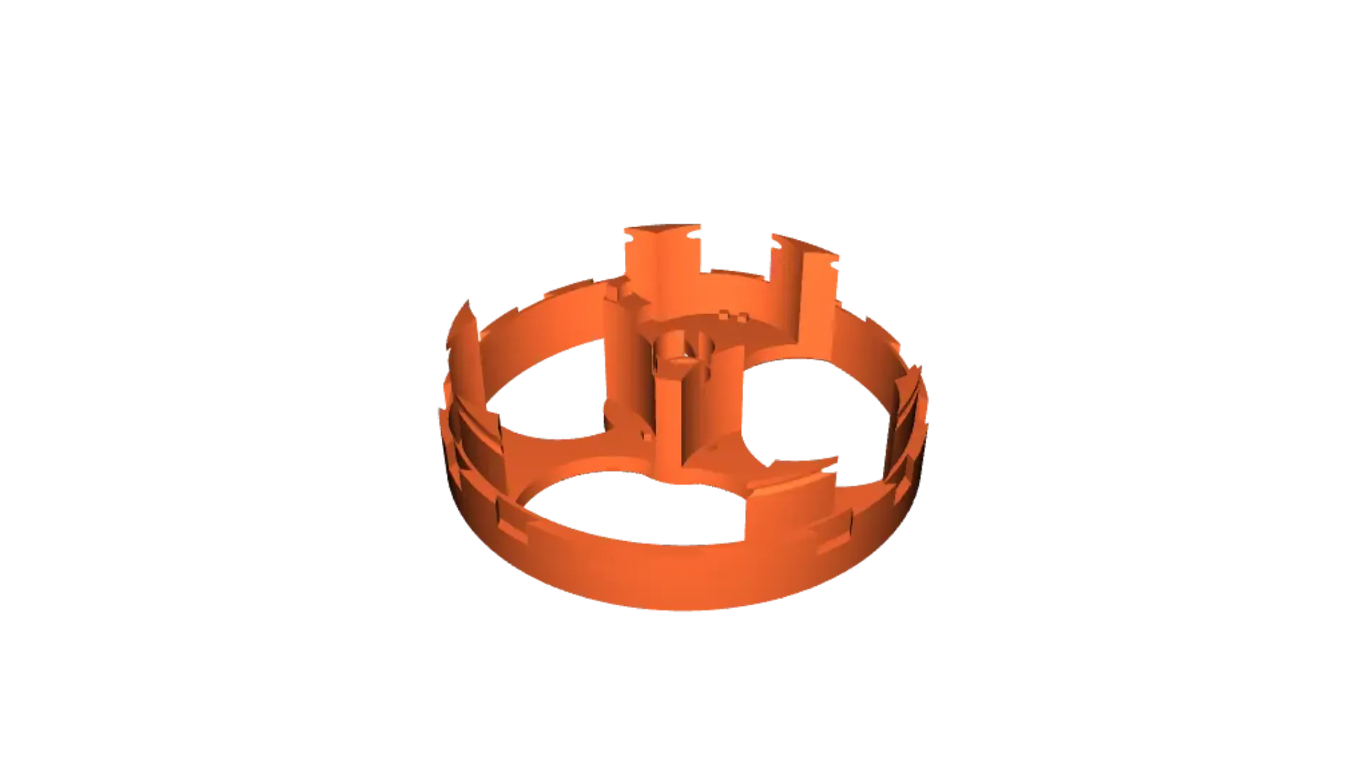
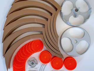
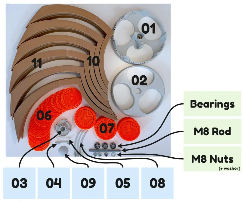
a. Overview
b. Printed parts
| Amount | Part | Description |
| 1x | 01-Rotary_disc_back | back disc housing the gears and interfacing with the wings |
| 1x | 02-Rotary_disc_front | front disc where wings attach to |
| 1x | 03-Release_disc | disc sitting in between front and back disc and releasing stored energy occasionally |
| 1x | 04-Lever_back | lever mounted to the back disc and preventing the release disc from spinning |
| 1x | 05-Lever_front | lever mounted to the front disc and triggering the energy release |
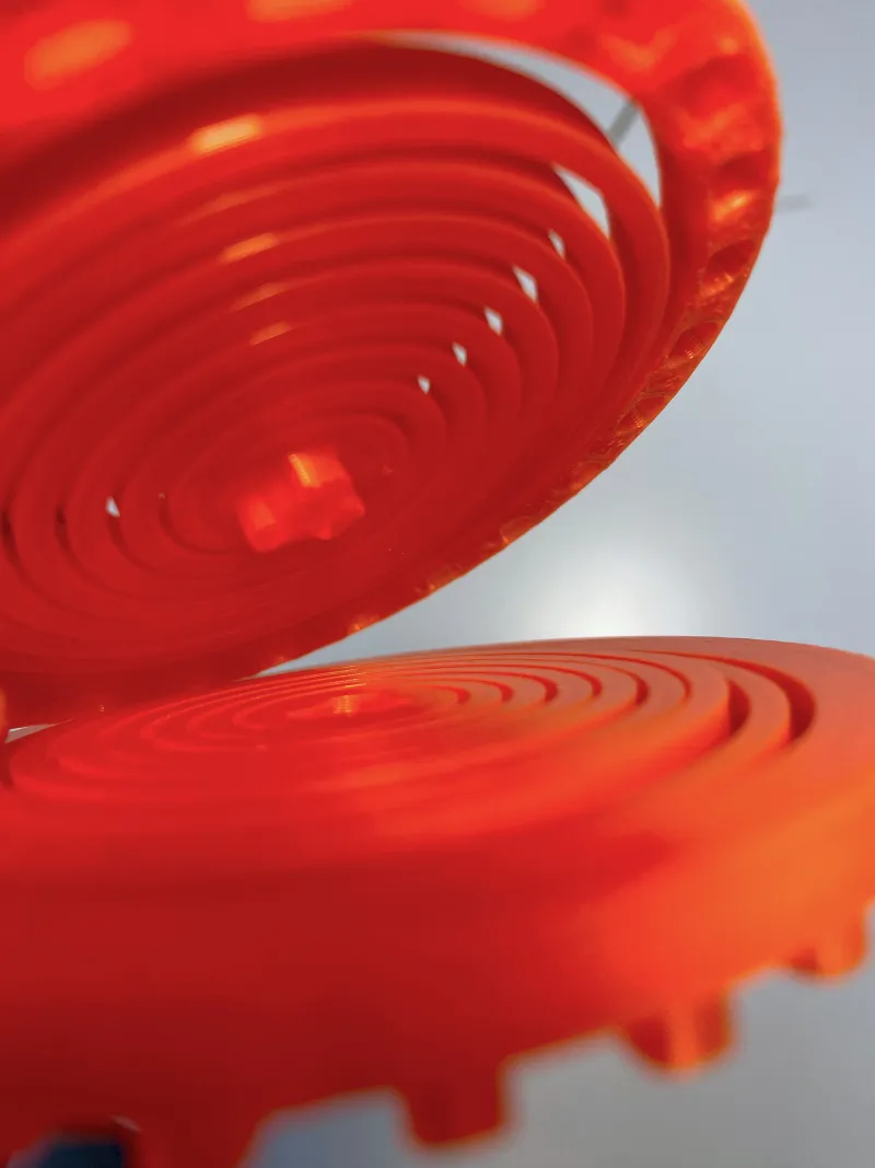
| 12x | 06-Spring_gear_type_1 | spring used to store the energy in the system by turing it clockwise |
| 12x | 07-Spring_gear_type_2 | spring used to store the energy in the system by turing it counter-clockwise |
| 3x | 08-Spring_gear_clip | clip securing the spring-gear-stack to the back disc |
| 1x | 09-Disc_endcap | cap sitting at the end of the rod on a nut, holding everything in place |
| 30x | 10-Wing_Part_1 | inner part of the wing that is attached to the discs |
| 30x | 11-Wing_Part_2 | outer part of the wing that is connected to part 1 |
c. External parts
| Amount | Part | Description |
| 3x | 608 ball bearing (8x22x7mm) | make sure to purchase low friction ones (without lubrication or with an open housing) |
| 1x | M8x110mm threaded rod | 120mm will also work depending on the mounting hole depth |
| 3x | M8 (self-locking) nut | at least ⅓ nuts should be self-locking (DIN 985 with a height of 8mm), the other two can be normal ones |
| 1x | something to attach the M8 rod to | (screwed) inserts, drive-in nuts, etc. |
d. (optional) Mounting options
As alternative wall mounting option, omgwtflolbbq designed a custom french cleat wall mount which should make the mounting process easier.
If you cannot or do not want to mount the sculpture on the wall, check out the optional display stand.
03. Assembly
a. Assemble all 30 wings by connecting part 1 to part 2. Put them aside for later use.
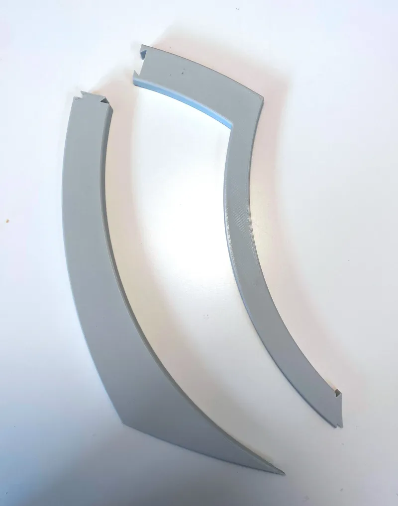 | 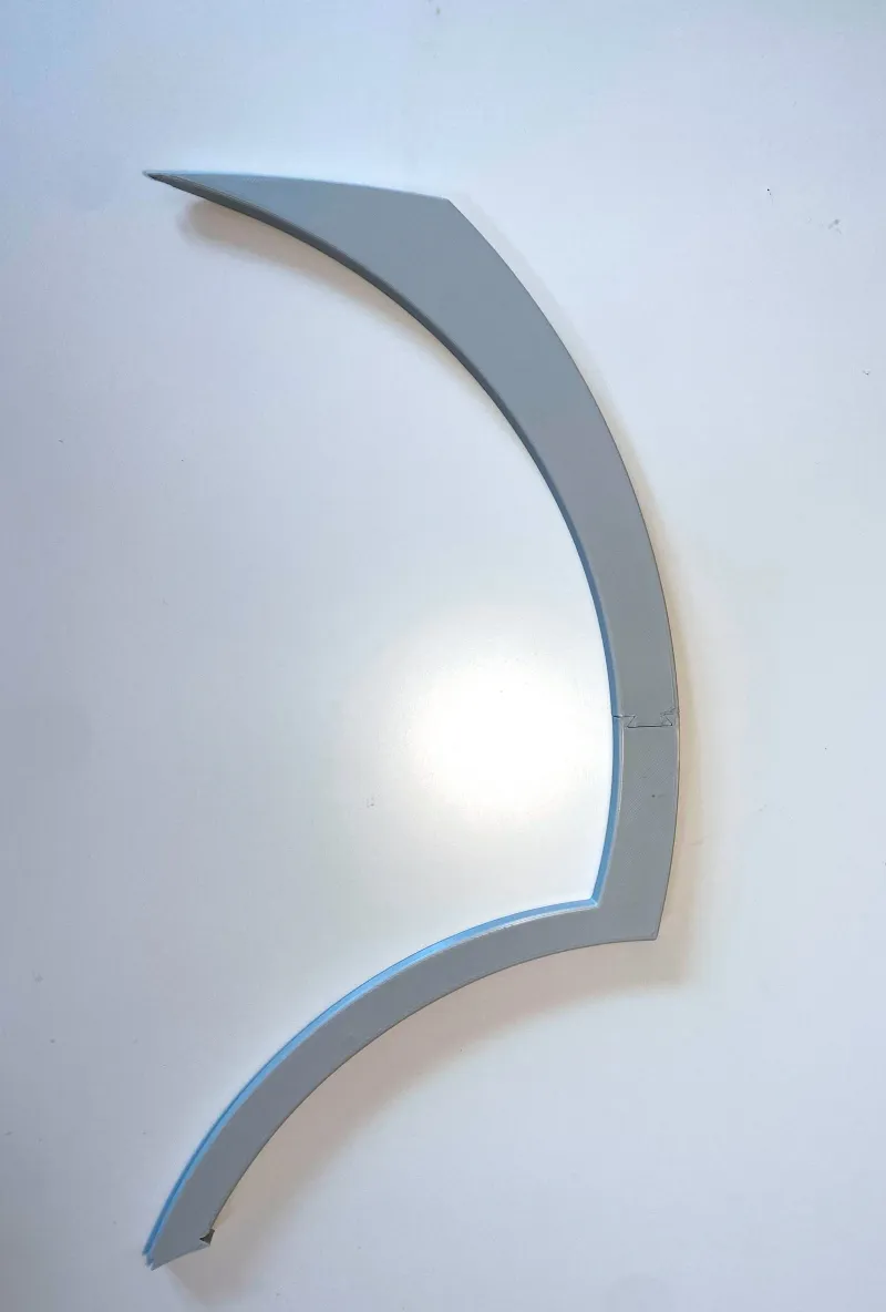 |
b. Take a spring gear type 1 and connect it via the middle pin to the back of a spring gear type 2 (see middle image). Repeat this step another 11 times.
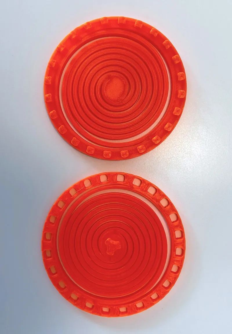 |  | 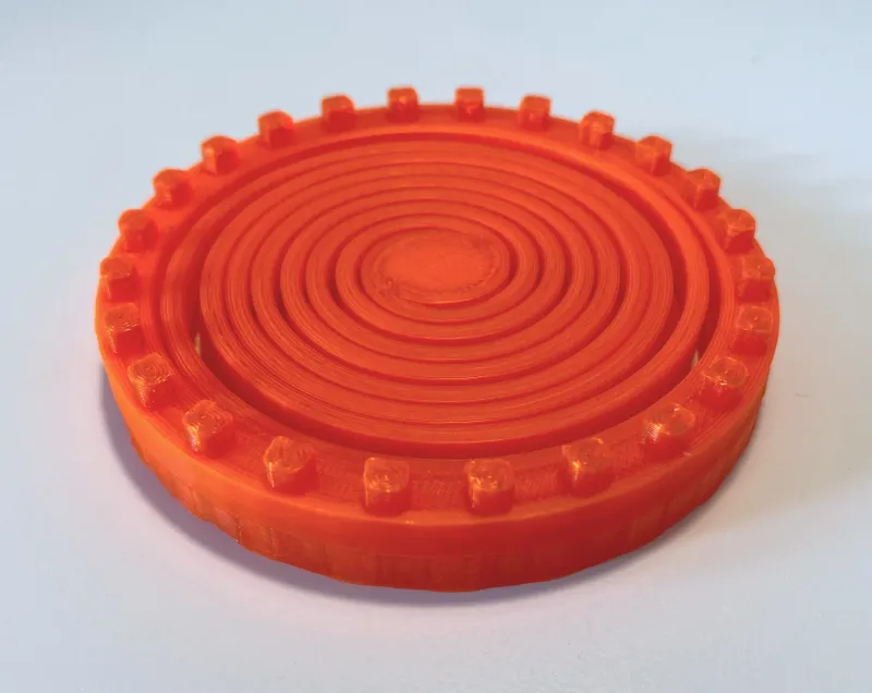 |
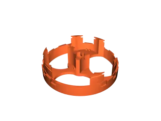
c. Take one of the just assembled gear stacks and stack it onto another one. Repeat this process two more times until you have a “gear-tower” consisting out of 8 gears in total (see right image). Following the same procedure, assemble the remaining two towers in the same manner.
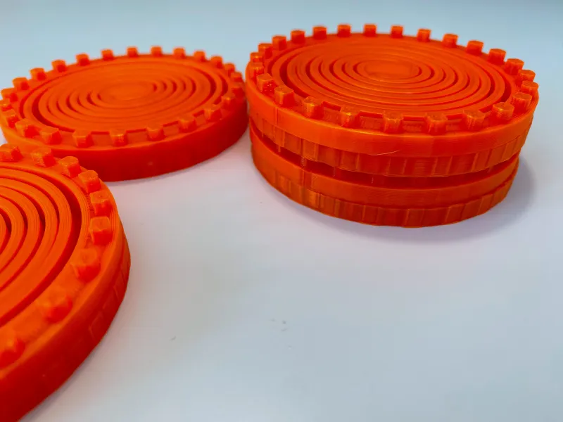 | 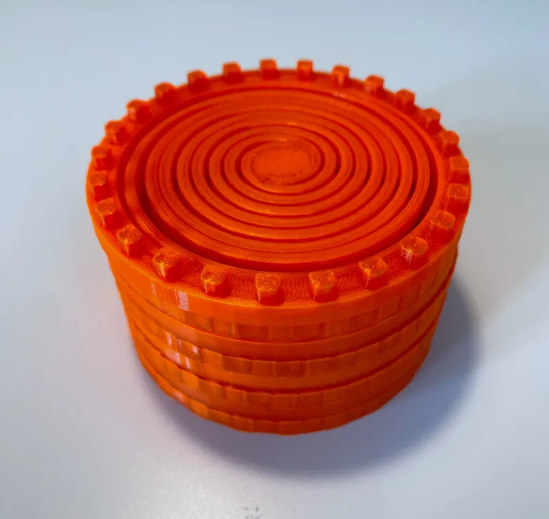 |
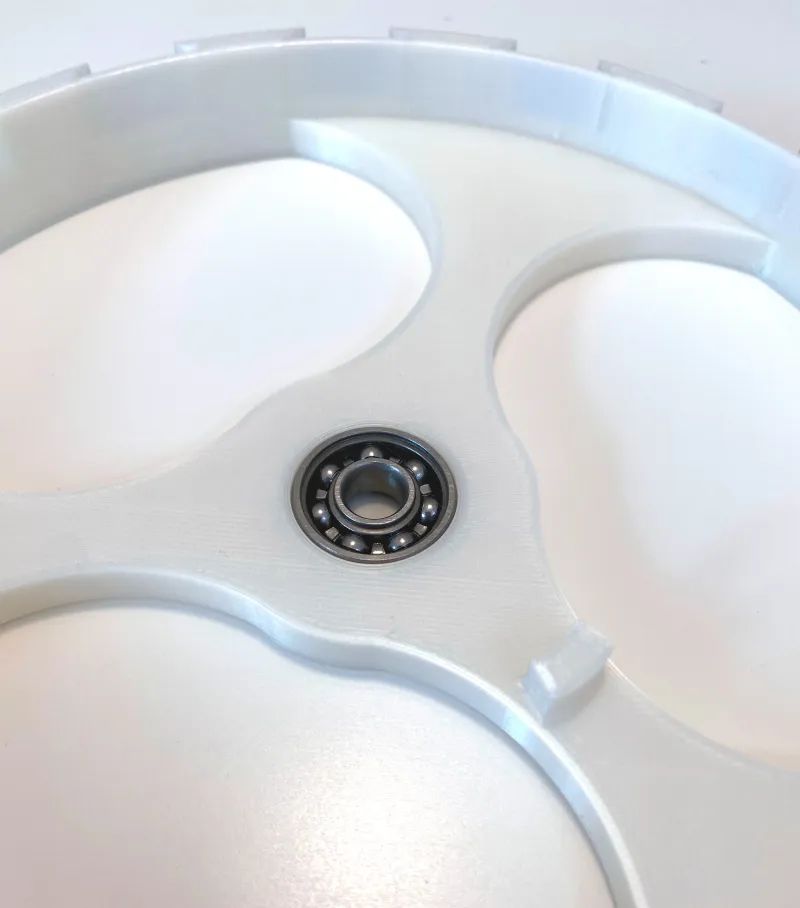
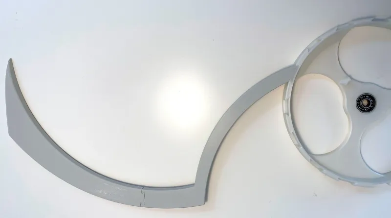
d. Take the back rotary disc and insert two ball bearings, one from the front and one from the back.
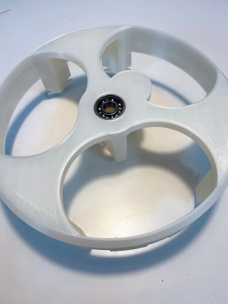 |  |
e. Getting 15 wings from the pile of wings assembled in a., connect them one by one to the back rotary disc by sliding them into the cutouts. Make sure that the narrow end of the wing is pointing in the same direction as shown in the image below.
 |
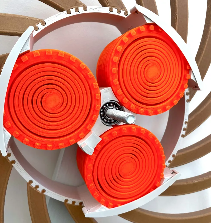
f. Insert the 3 gear-towers from c. into the back rotary disc. Make sure the pins on the back align with the lower gear such that it cannot rotate anymore when attempting to spin it from the outside.
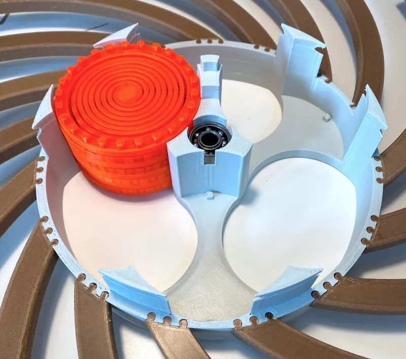 | 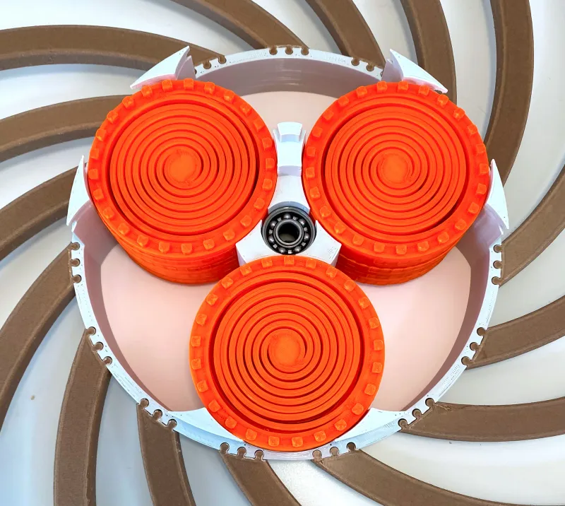 |
g. Use the 3 spring gear clips to secure the gears in place as shown in the image below
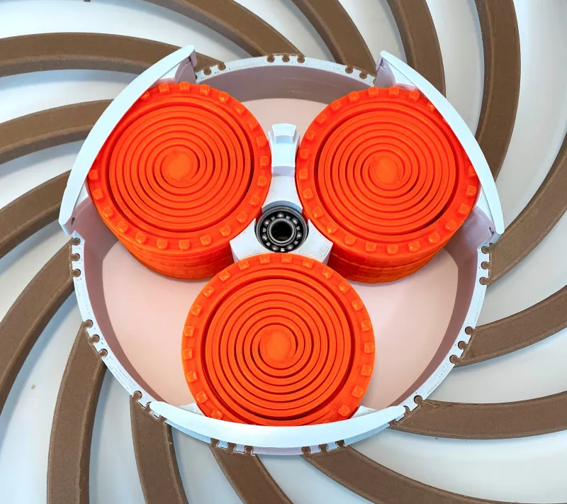 |
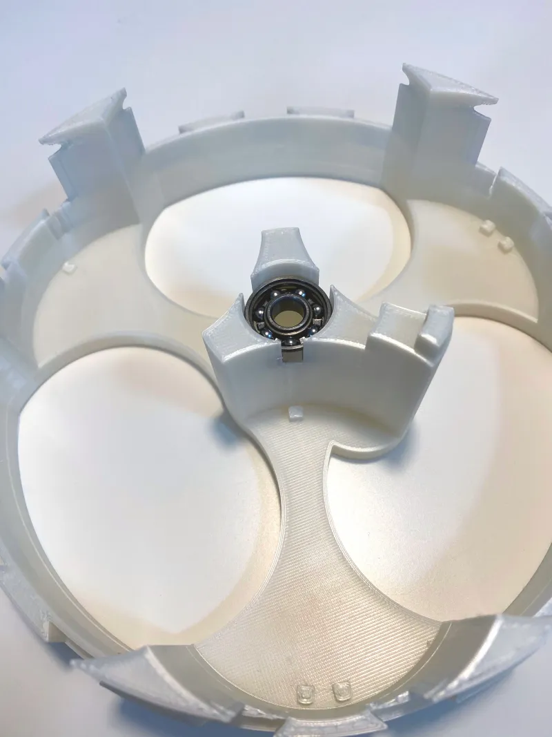
h. Insert the last ball bearing in the front rotary disc.
 |
i. Install the front lever on the inner side of the front rotary disc such that the pointy end sticks out (see image).
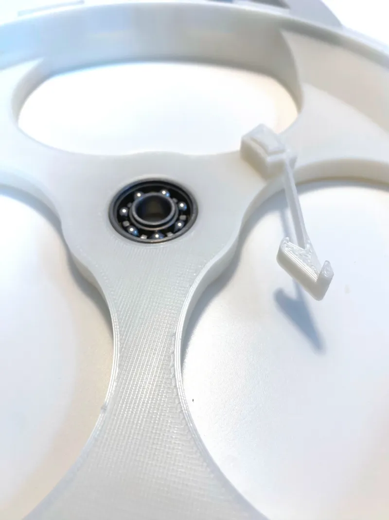 |
j. Take the remaining 15 wings and insert them into the disc similar to step e. Make sure that their orientation matches the one displayed below.
 |
k. Prepare the location you intend to mount the sculpture to (wall or display stand) by drilling a hole and inserting a drive-in nut (for example). Screw in the threaded rod roughly 10mm and secure it in place by tightening a M8 nut against the wall/stand.
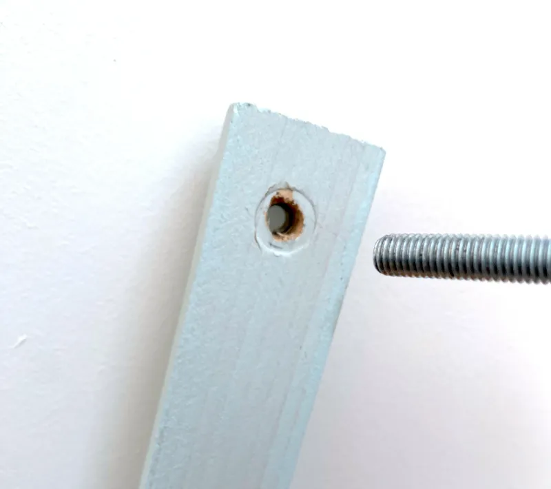 | 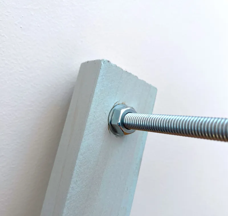 |
l. Slide the back rotary disc onto the rod and push it all the way to the end.
 |
m. Stick the release disc onto the rod and into the back rotary disc. Secure it in place with the self-locking nut but make sure to still leave a bit of room for it to spin freely. Tightening this nut too strong will affect the overall performance of the sculpture negatively by inducing too much friction.
 |  |
n. Install the back lever onto the back rotary disc such that the raised side is pointing towards you. Rotate the release disc a bit so it is resting agains the lever like shown below.
 |
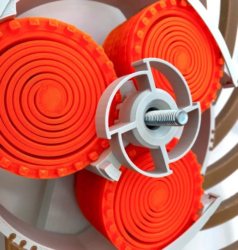
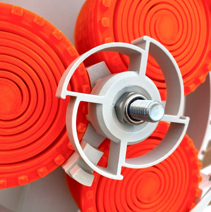
o. Slide the front rotary disc onto the rod and push it all the way through until it makes contact with the self-locking nut.
 |
p. Prepare the endcap by inserting a M8 nut into the cutout like shown below.
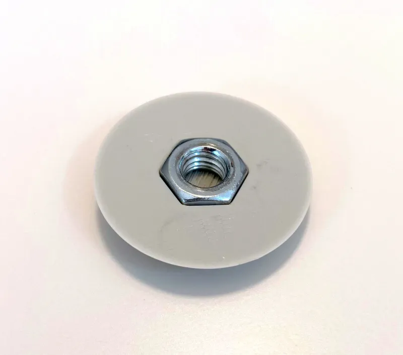 |
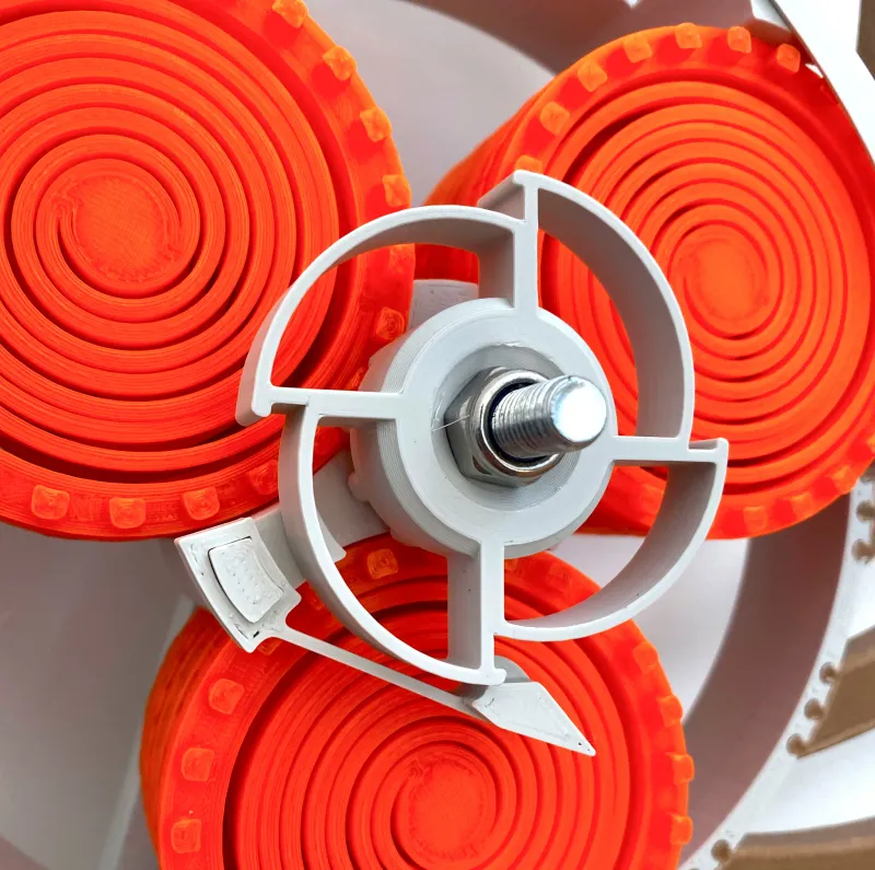
q. Screw the endcap on the rod and tighten it firmly against the front rotary disc. Everything should be secured in place now and your sculpture is ready for its first spin (make sure to read section 04. beforehand)!
 |
04. Startup

While carefully holding a wing of the back rotary disc, use your other hand to turn the front rotary disc clockwise. As soon as the front lever slides underneath the back one, it should hook into the release disc and start winding up the springs. Count the number of times you hear a clicking noise produced by the back lever sliding over the release disc and stop the windup sequence latest by the 20th click (equals five full turns by the front rotary disc, I usually only do 4.5 turns to be on the safe side). Winding up the sculpture even more at this point might damage the springs or deform them permanently. Now the only thing left to do is to give the two discs a slight push (clockwise for the back one and counter-clockwise for the front one), followed by leaning back and enjoying the movement of the sculpture.
For visual guidance, take a look at the gif to the right.
05. Known issues and how to fix them
a. The release disc does not rotate smoothly.
- Solution: Give it a couple of spins by loading the springs and then releasing it again by lifting up the lever. But be careful not to stick your fingers into the release disc while spinning! If that does not solve the problem, try to loosen the self-locking nut a bit.
b. The front lever scratches on the back one.
- Solution: They're most likely not properly installed. Push them all the way onto their mounting pins and make sure they rotate parallel to one another. If that didn't help, check if the back and front disc are properly aligned.
c. The front lever resonates when sliding over the back one.
- Solution: Although this problem should not occur anymore, just bend the front lever a little bit outwards. But be careful not to bend it too much, otherwise you might break it apart.
d. The back disc experiences too much friction, either slowing down too fast or getting stuck.
- Solution: Check the ball bearings if they rotate smoothly given a spin by hand. If that's working fine and the problem persists, loosen the self-locking nut a bit to reduce the friction at the release disc.
- As an indicator of how well your system is working, you can use the reference below: Remove the front rotary disc and align the back lever mounting pin (red box) such that it is upside down to its usual resting point (0° mark). Remove your hands, let it rotate freely to the left and observe how far it moves until it reaches the turning point. Reaching the yellow line (270° of rotation) would be an acceptable outcome but crossing the green line is ideal. Anything less than that requires recalibration (loosening the nut, exchanging or cleaning the bearings).

06. Remarks
Last but not least, here are a few things you should pay attention to:
- Don't overload the springs: As already mentioned in chapter 04., spin the front rotary disc for not more than 5 turns during windup. Otherwise things might break or deform.
- Don't stick your fingers into moving parts: Don't grab into both spinning discs at once and especially don't grab into the release disc when the springs are fully loaded and the lever is pushed out of the way manually. It can get quite fast and therefore hurt quite a bit when hitting a finger.
- Good bearings are key: The smoother the ball bearings rotate by themselves, the less energy will be lost due to friction later on when the sculpture is moving. This results in longer runtimes and therefore more watch time!
Looking forward to see your builds. Happy making!
----------------------------------------------------------------------------------------------------------------
Changelog
15.10.2022 - Added .step files and estimated filament requirements based on my experience
20.10.2022 - Added chamfers to spring gears for better printing results & easier assembly
25.10.2022 - Refined rotary disc front by removing thin walls of front bearing cutout
26.02.2023 - Added reference to display stand.
02.03.2023 - Referenced omgwtflolbbq's design “french cleat wall mount” to the manual
Tags
Herkunft des Modells
Der Autor hat dieses Modell als seine eigene Kreation gekennzeichnet.

