Chat-To MultiBand Vertical Antenna Kit Ultra Portable SOTA POTA HF HAM


Description
PDFthe Chat-To Antenna
from the word “castle” due to the design shape
this is my version of the famous vertical “manpack” antenna. i had to buy alot of stuff and the total cost is almost the same as the commercially available Chinese version (PAC-12) please consider the cost before starting this project. as mine is a bit better in some aspect, but i wish i knew this before starting this project. as i was originally doing it to save money… some similar commercial version are close to 500$ USD (CHA) so it all depend on you.
this is a resonant antenna and doesnt require a tuner.
UPDATE july2024:
i made an alternative design that is utilizing only M10 threads. it enables you to use commonly found and cheap telescopic whips, loading coil and ground spikes. check it out on my other design page. [M10 Manpack vertical Antenna]
UPDATE:
i just added a “short body no tube no coil” file. it is in order to use the highter frequency without having to short the coil or even bent your antenna in order to tune it. for example on 10M (28mhz). the stock whip and extension tube make for a hard to tune antenna. with this version of the body you can just have the ground spike and whip! no need for the coil and no extension tubing.
Feature video:
(the parts in those videos arent the most recent design)
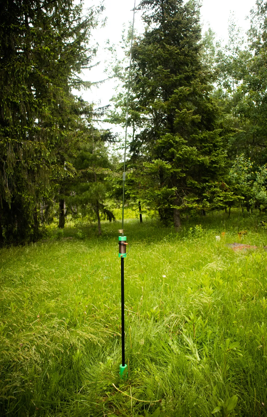
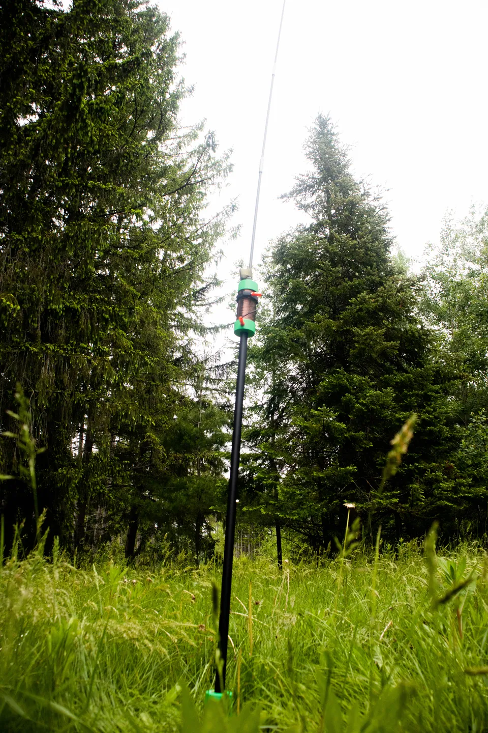
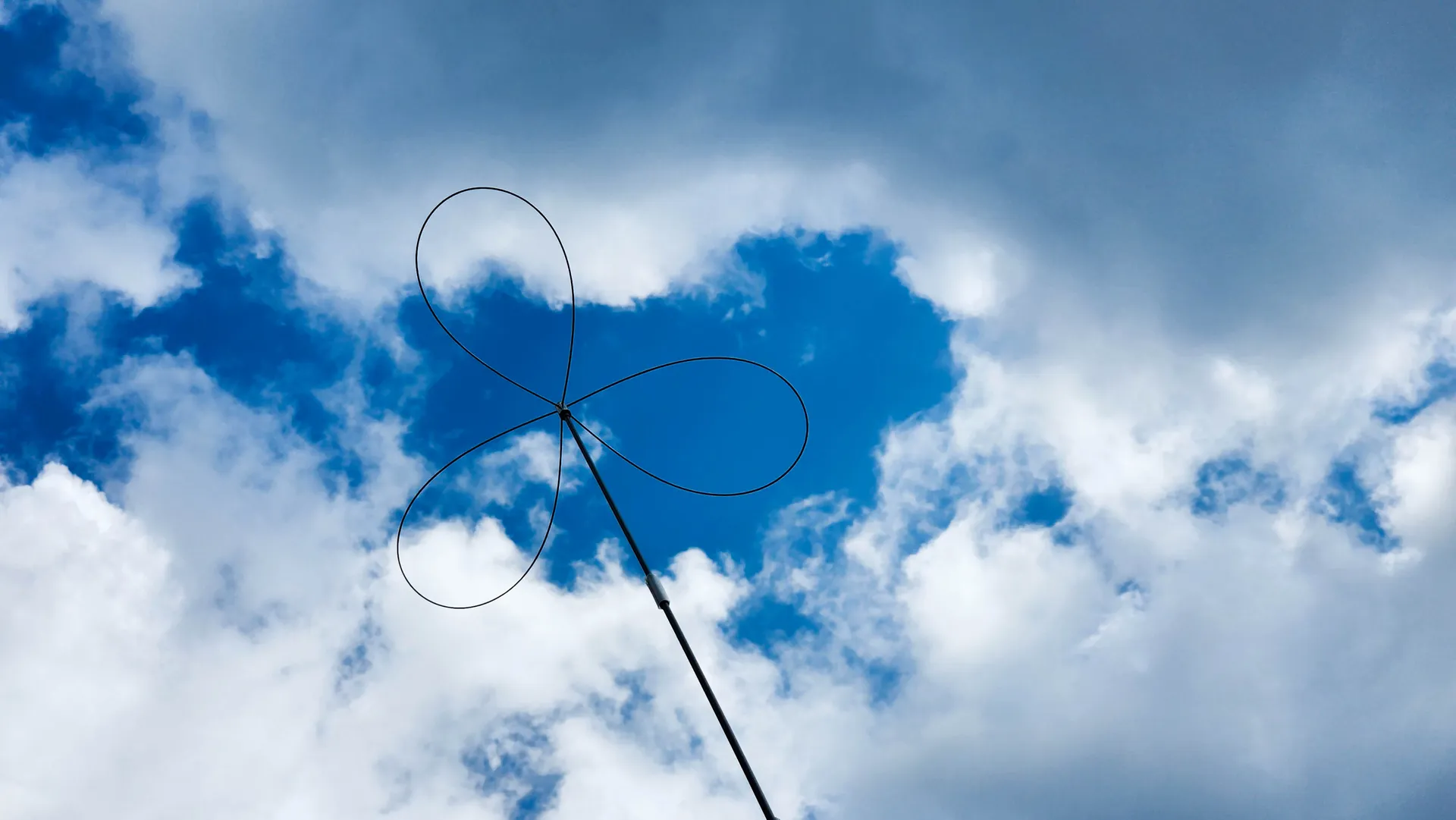
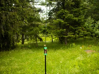
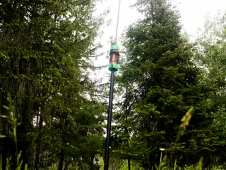
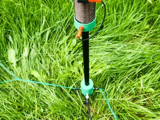
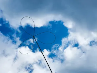
Field Deployment:
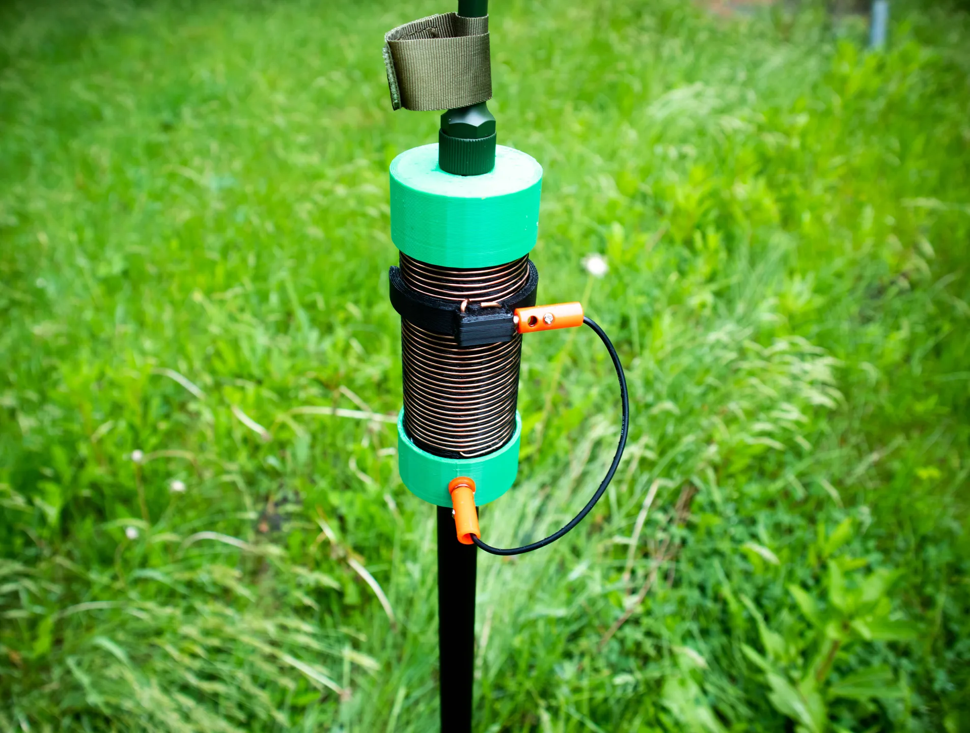
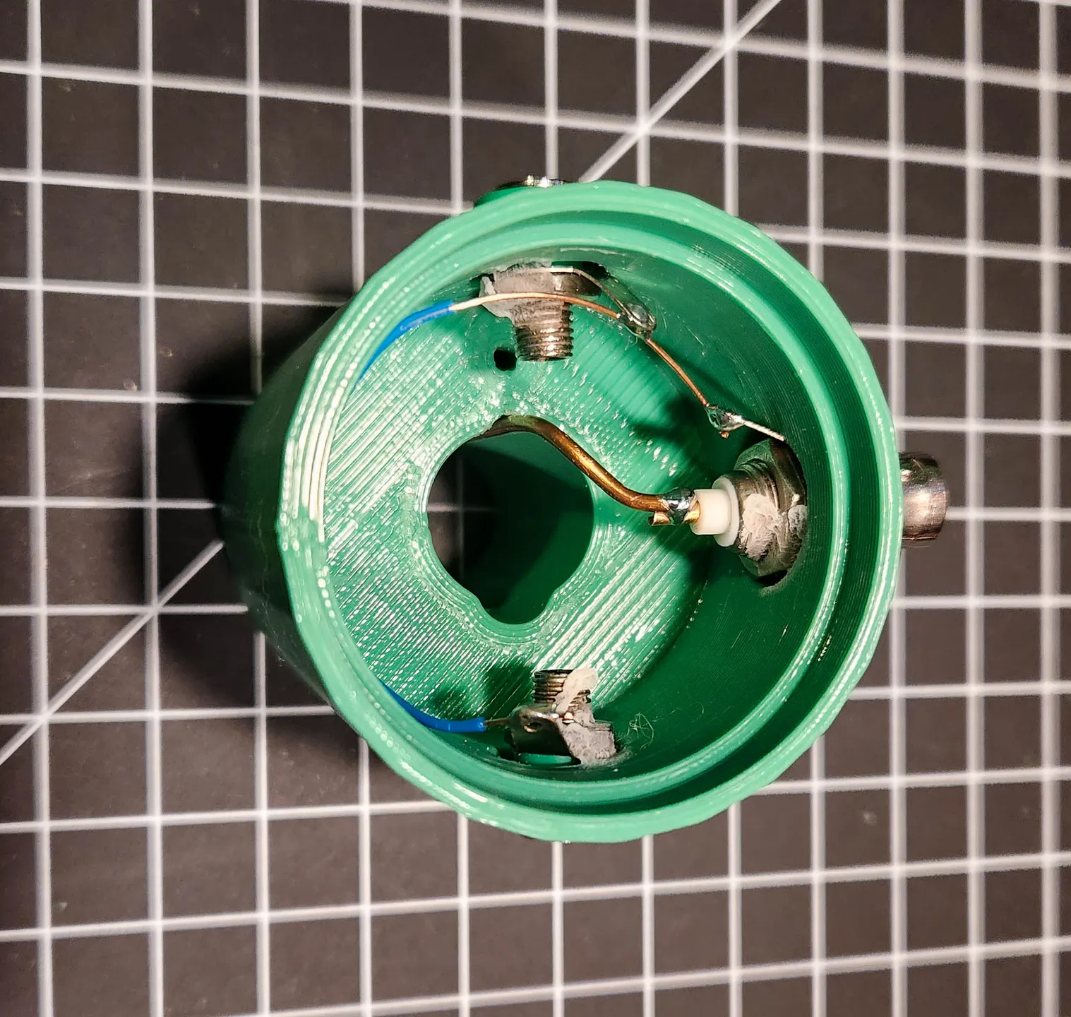
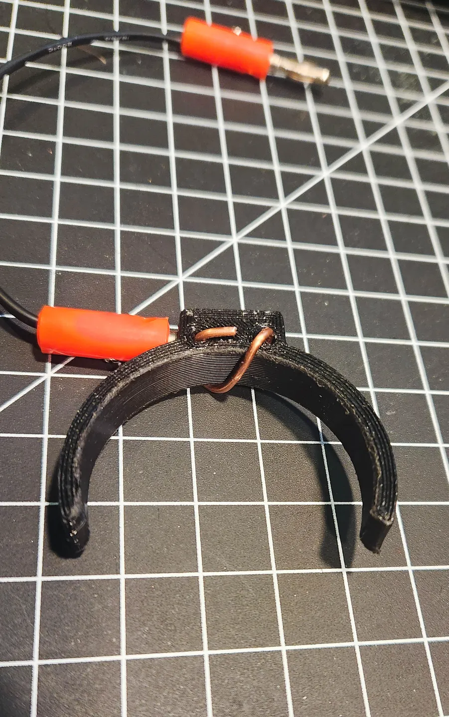
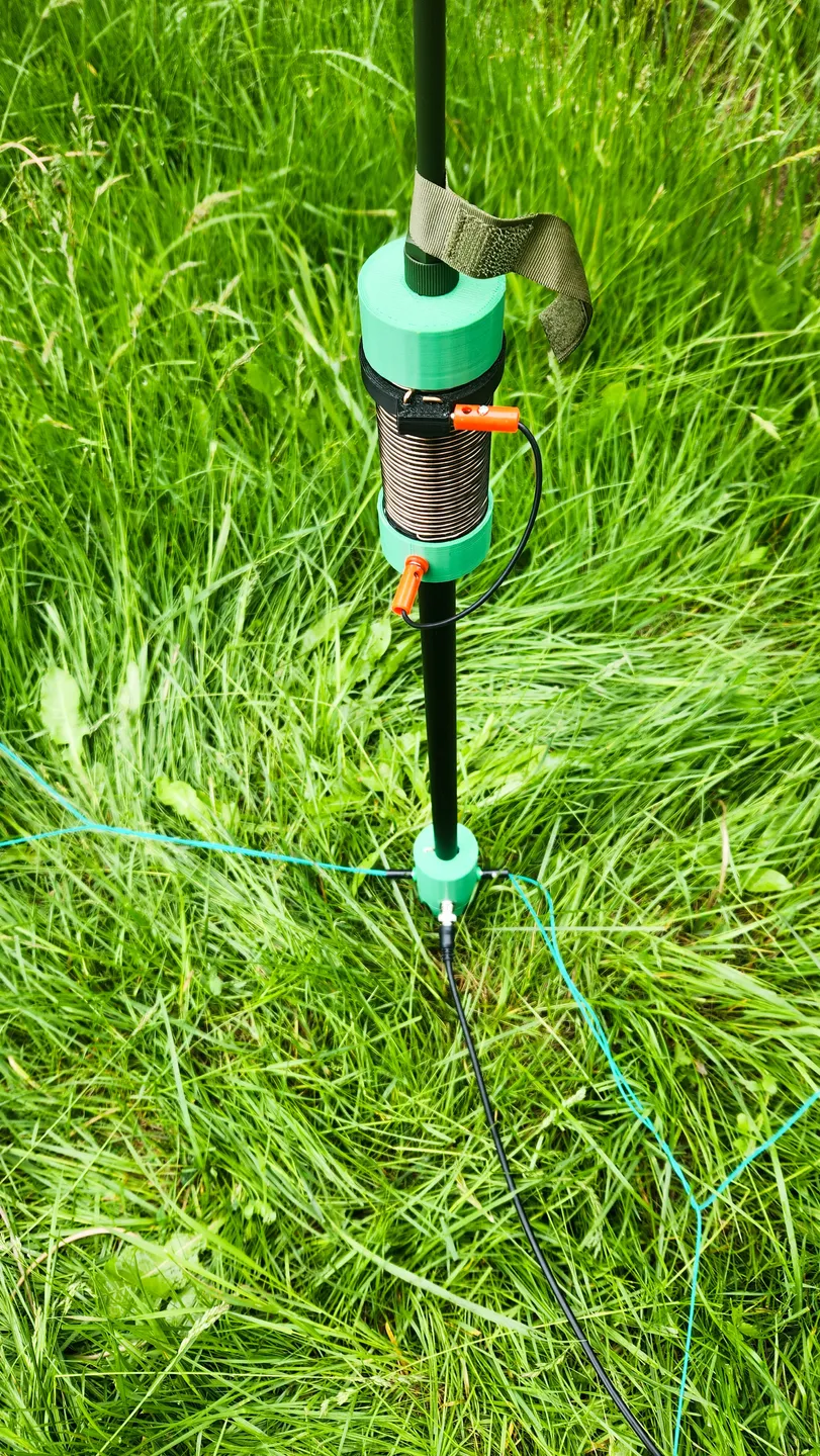
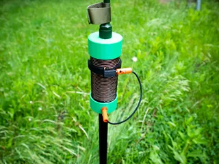
close-up of Features:
Base Options:
it is quick to assemble, and is fairly durable. in my non-engineer opinion the weakest point is the male part of the coil base. i haven't found a way to make it super strong yet. if your printer is well set and your filament is fusing correctly it is still perfectly usable without “babying” it.
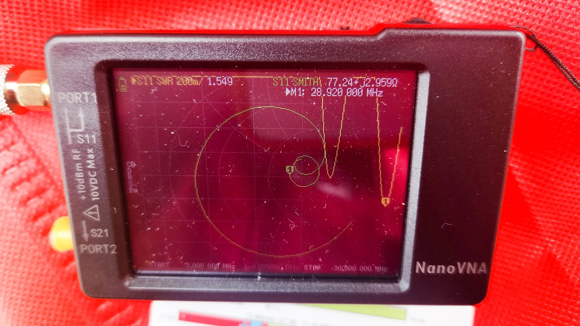
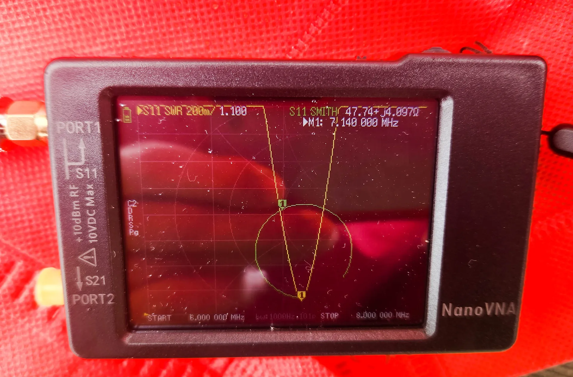
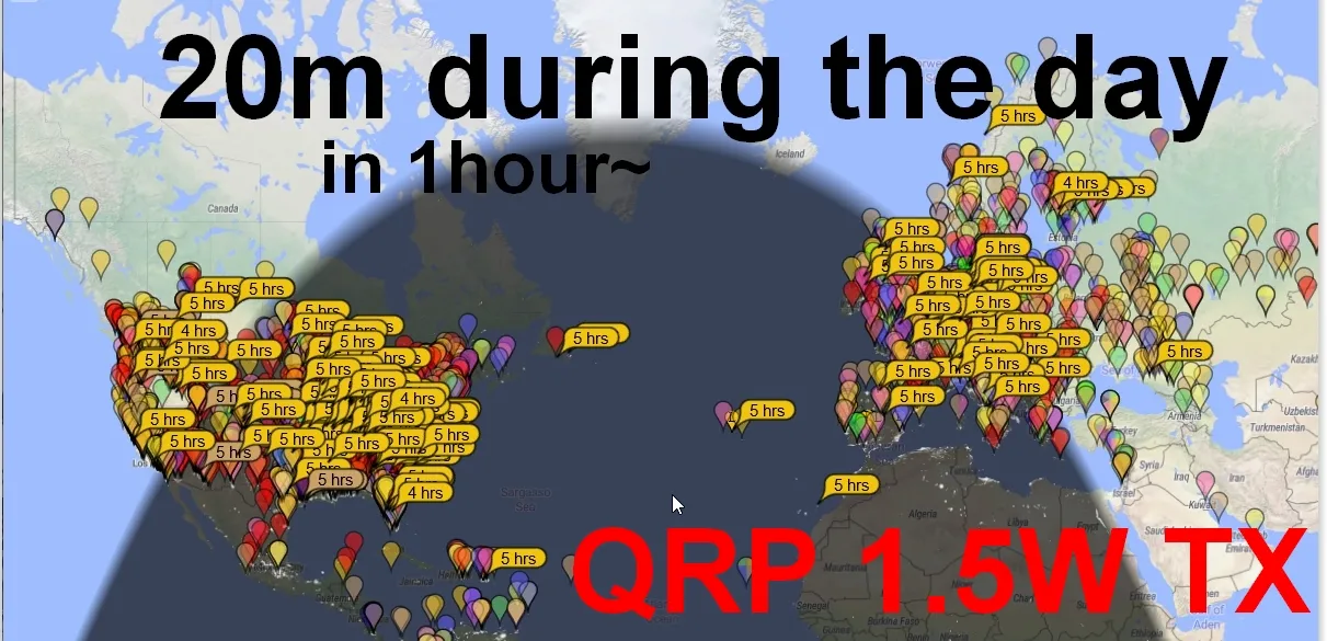
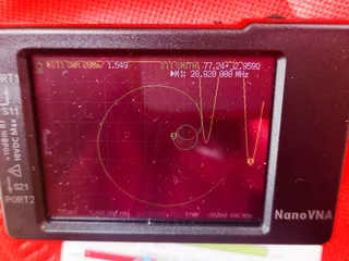
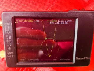
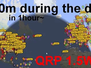
Tested from 40 to 10m successfully my results:
40m band 1.1 SWR
10m band 1.5 SWR
remember there are 4 possible adjustment with this setup. the whip, the coil, the extension and finally the radials. you can possible tune to any frequency between 6 and 30mhz easily by playing with each possible combinations of the kit. this is never perfect, but good enough and way better than some model that use a matching transformer or even a dummy load to cheat the results.
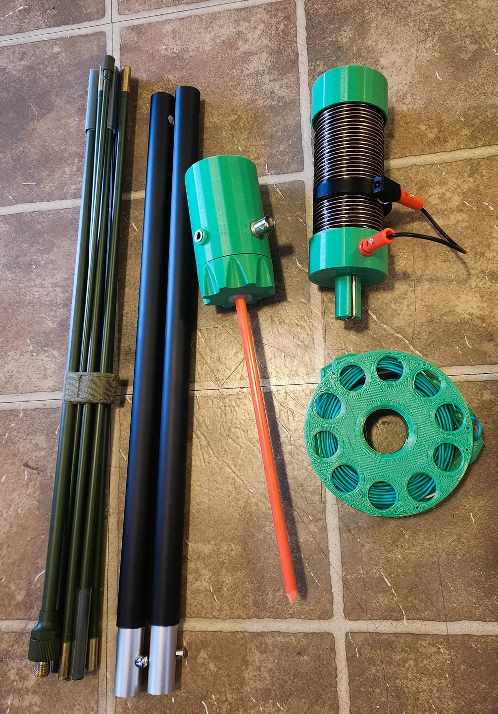
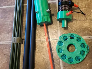
[material list]:
- all the 3D printed parts (choose your base option)
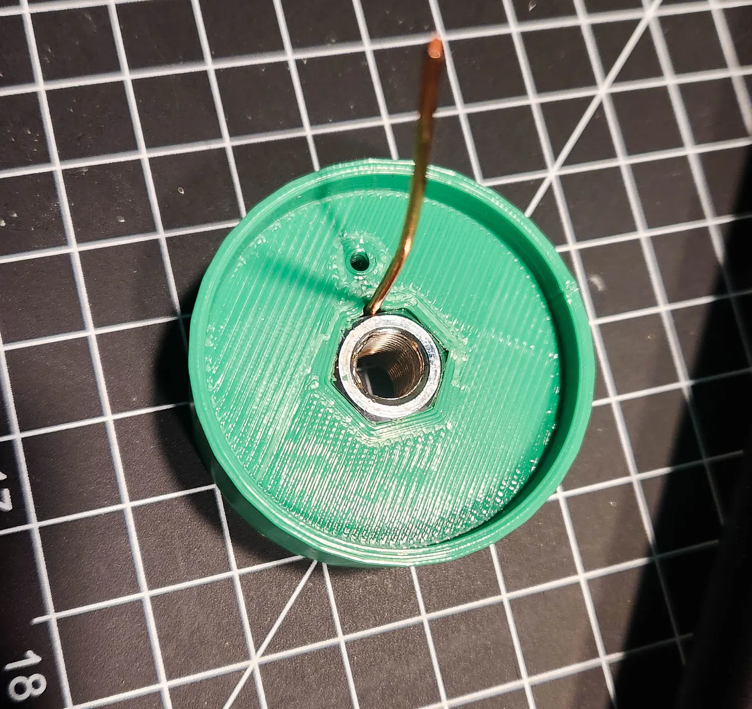
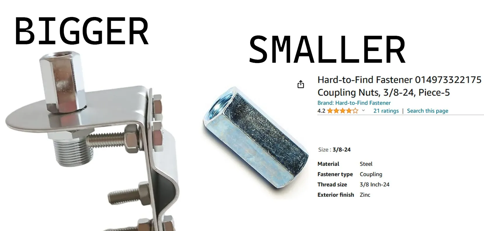
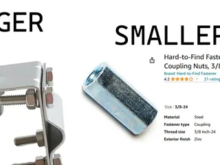
- antenna mount nut (cb style, mine was 2cm tall) 3/8" X 24pitch
- collapsible whip antenna (similar to AT-271)
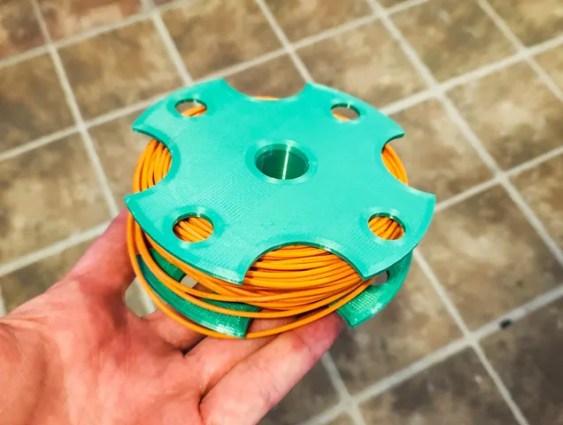
- 4X 17ft radial wires
- 3X banana plugs set +1male
- 5m~ of 20ga copper wire
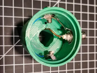
- BNC pannel mount connector
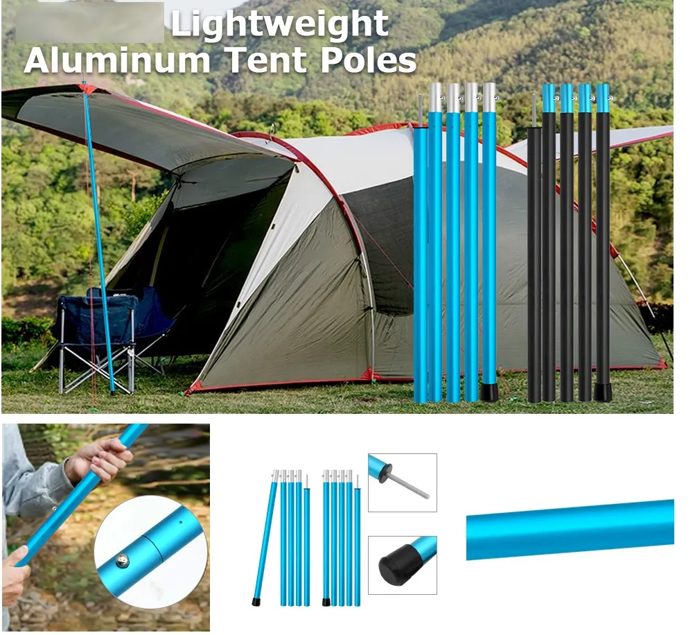
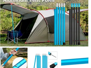
- 2 to 3 length aluminum tarp pole support (19mmOD 17mmID 42cmL)
- piece of extra wire and hardware for soldering
- 14-16ga copper wire solid core
- a 8mm~ stake OR aluminum ground spike OR photograph tripod
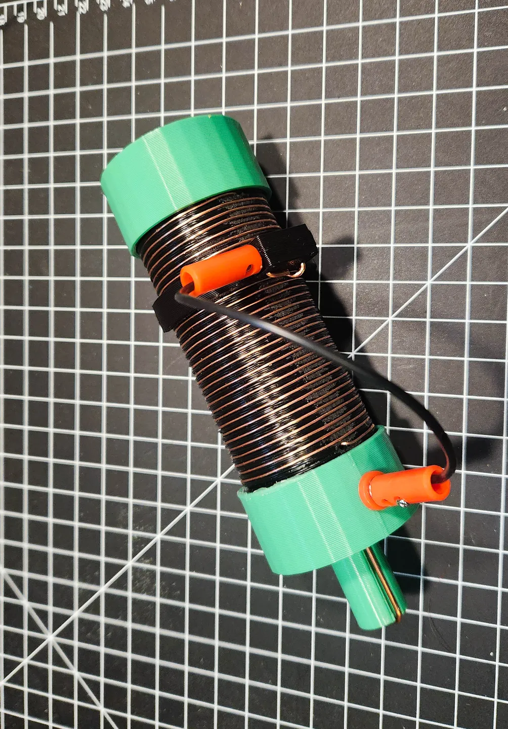
[Assembly note]
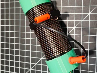
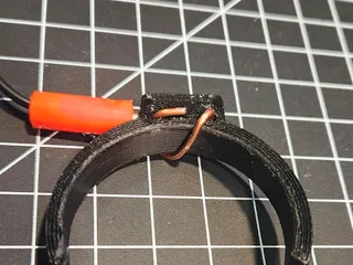
you need to file down a flat spot into the coil in order to make the copper wire stand-up a little from the rest of the coil and provide good connection for the slider. you can also play with the print setting a little if your clip is a little too loose or too tight.
if you are planning on using it outside in very hot weather, use white PLA-plus or other more resistant plastics for the print. as the normal PLA could theoretically soften a little bit from the solar radiation. it never happened to me, but it is possible.
the aluminum pole are electrically connected to the assembly by forced mechanical/electrical connection with a length of bare copper wire. they act as the bottom part of the radiating element in order to bring the loading coil up, thus “center loading” the antenna. the measured resistance is less than .2ohm across the entire length of the assembly. be careful of your printer setting as the tolerance is a bit tight and important compared to most of my other design. a good set of files are your friend! in the pictures is a mixture of newer version and past. i cant be bothered to re-print and re-assemble all of it for myself as my current setup is working 100%. the newest version are tweaked and better looking.
the coil part is modified from another design, as it is impossible for me to make some with tinkercad. original by waveforms thingiverse.com/thing:4938282
the spool i am using to hold my radials is resized 50% from: @Chrizz printables.com/model/392066
[HELP WANTED]: if somebody could redesign the coil part in order to have a easier to print groove profile instead of the V shape. because mine has artefacts in some place and doesnt print to cleanly.
WARNING
some 3/8X24 nut are smaller (thinner) than the others. i am currently remaking some parts for the smaller nut. my original parts where made for the bigger nut that is commonly sold with a bracket.
if you love this and it is useful to you please post a MAKE!
Tags
Model origin
The author marked this model as their own original creation.